
4. Functions of Project Management
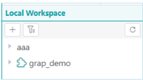
When opening the Editor software, all locally existing programs will be listed.
The function pages are shown in the following image:
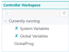
After connecting to the controller, the programs on the controller will also be listed, as shown in the image below:
(1) Workspace expansion
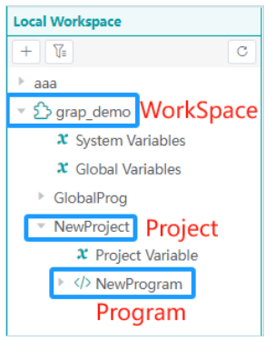
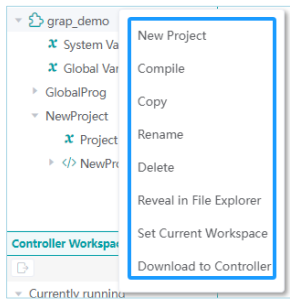
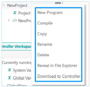
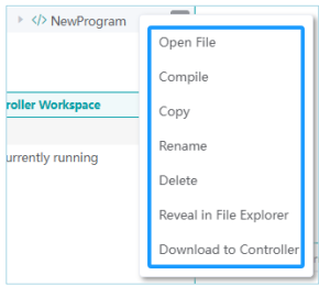
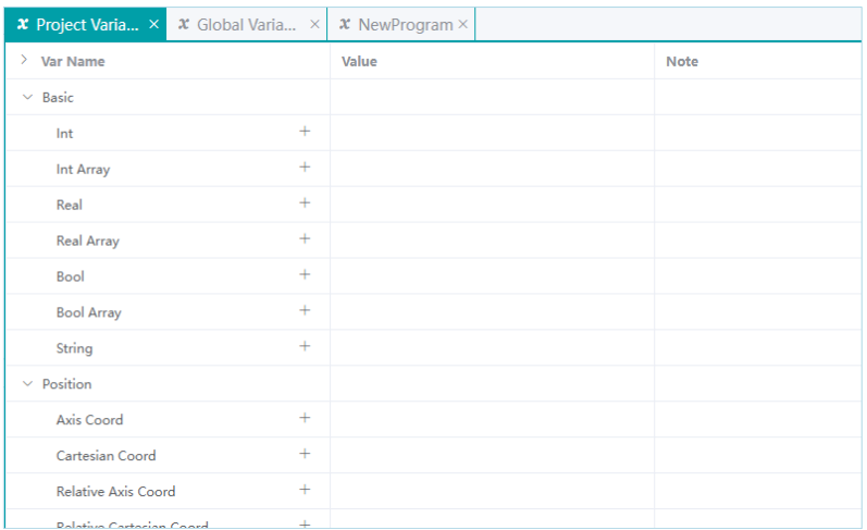
(5) Double-clicking on a node (global variable, system variable, project variable, program, program variable, other nodes not supported) will display it in a tab, as shown in the image below:
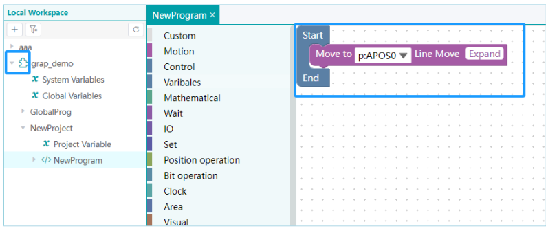
If it is a graphical function, the program will display a graphical interface.
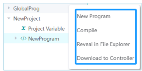
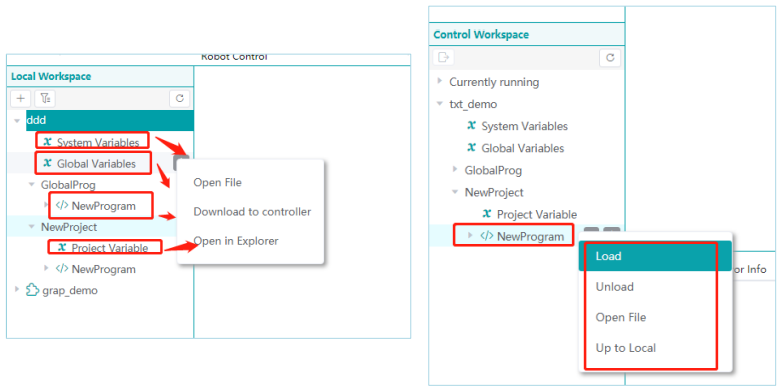
For the right-click menu of global variables, system variables, project variables and program files, it will be opened using the Windows self-contained program, as shown in the image below:
4.1.Differentiate Icons in Project Management
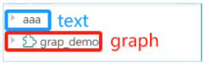
Text files and graphical labels are distinguished by an icon.
4.2.Global Project
Each workspace has a unique global project named "GlobalProg". It cannot be deleted, renamed, or copied.
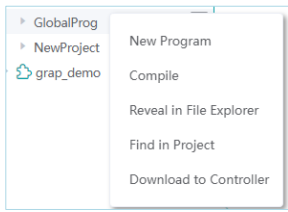
It does not have project variables and supports the following operations. These operations are the same as regular projects, and all other projects within the workspace can use its programs.
4.3.Create a New Workspace
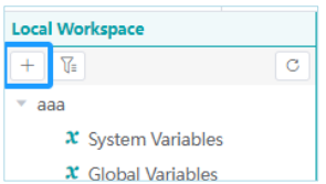
Click the "+" button to create a new workspace.
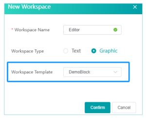
Within this window, you have the option to select the creation of either a text-based project or a graphical project. It's important to note that the program initiates the creation of a 'graphical workspace' by default.
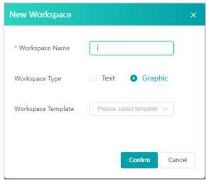
If creating a graphical workspace, you have the option to choose a workspace template, as illustrated in the following image:
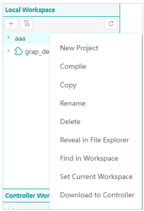
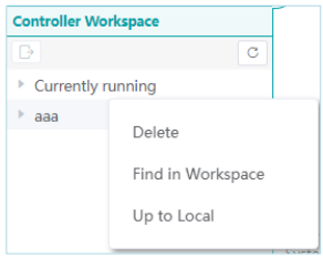
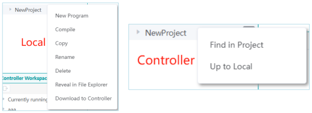
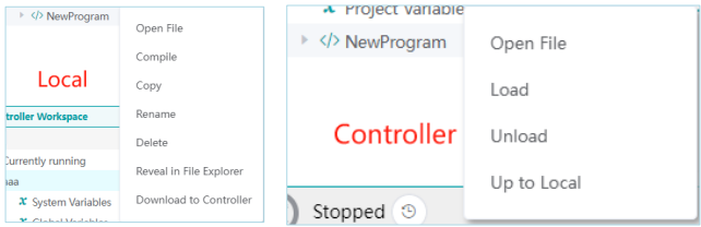
Server workspace supports the following operations:
4.4.2.Project
4.4.3.Program
4.4.4.Variable File
4.5.Variable Module
The variable module includes system variables, global variables, project variables, and program variables.
System variables cannot be edited, and each variable type has its own set of permissible variable \ creations.
4.5.1.System Variables
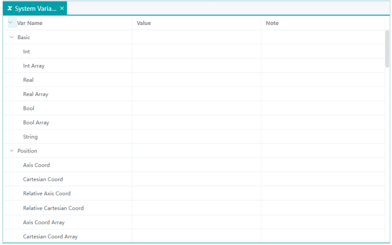
System variables cannot be modified, they can only be viewed. Double-clicking on the system variable node in any workspace opens it. Programs throughout the workspace can use these variables, as shown in figure below:
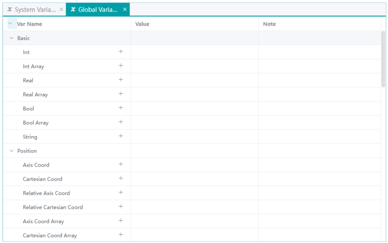
4.5.2.Global Variables
Global variables encompass all variable types, support adding, modifying, copying, and deleting functions.
Programs throughout the workspace can use these variables.
4.5.3.Project Variables
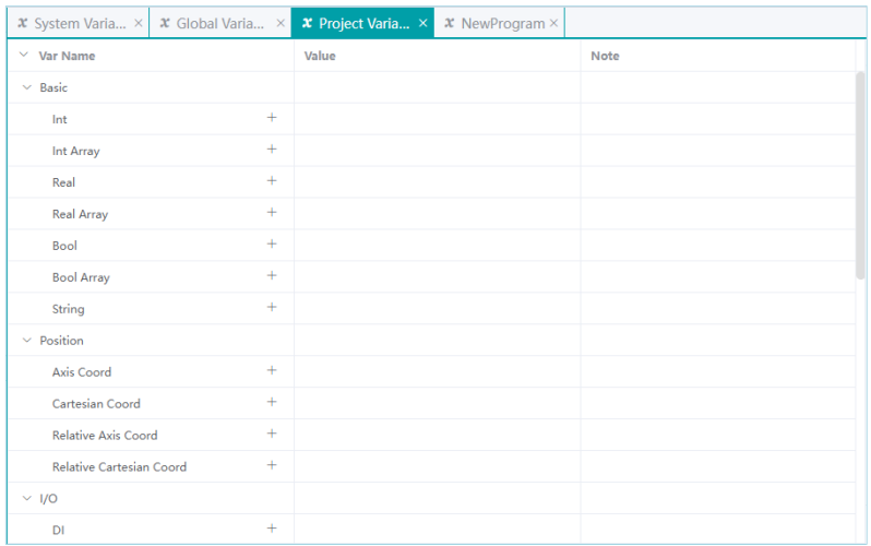
Some variables can be added, but only programs within the current project can use them.
4.5.4.Program Variables
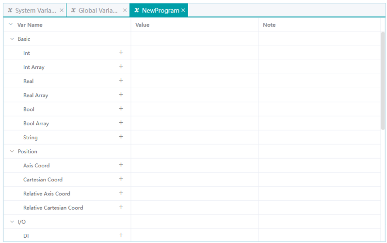
Only the current program can use these variables.
4.5.5.View, Modify and Save Variables
After opening or creating a workspace, double click on the corresponding variable node icon in the resource tree to open the UI page for that variable file on the right side.
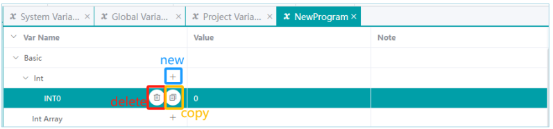
4.5.6.Create/Delete/Copy Variables
Variable Creation, Copying and Deletion
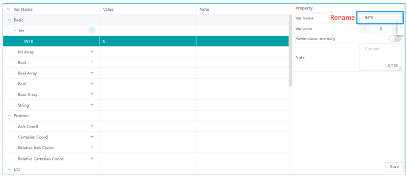
4.5.7.Rename Variables
To rename a variable, select the variable in the table, edit its name, and click "Save".
4.5.8.Variable Comments
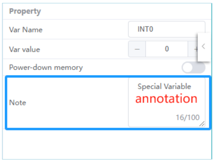
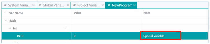
To add comments to a variable, select the variable in the table and enter the comments in the "Variable Comment" section on the right. Click "Save" to save the comments. The comments will be visible when the project is opened.
4.5.9.Modify Variable Attribute Values
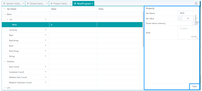
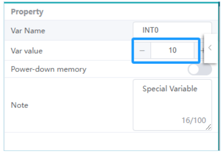
Click on a variable row in the table, and its current attribute values will be displayed on the right-hand side.
Modify the desired attributes in the "Attribute" page. After making the modifications, click the "Save" button to update the variable table with the new attribute values, as shown in figure below. Please note that clicking the "Save" button is necessary for the changes to take effect.

4.6.Program Editing
Users can conveniently edit and modify programs using this software. The program editing UI is displayed as follows:
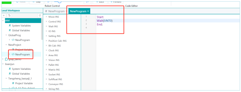
(1) Double-clicking on a program node in the project tree opens the corresponding program for editing.
(2) The program editing area provides flexible and convenient text programming editing operations.
Common text shortcuts are supported, such as Ctrl+C for copy, Ctrl+X for cut, Ctrl+V for paste, Ctrl+Z for undo, and Ctrl+Y for redo. Users can also use the toolbar in the program editing UI to perform corresponding operations.
(3) Program commands and keywords are highlighted for easy visibility.
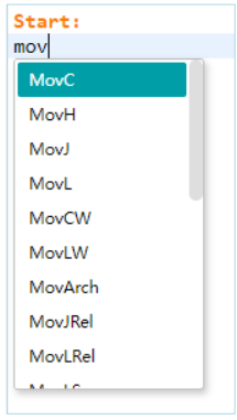
(4) Auto-Suggestion functionality is available for code input (variables, commands, etc.) within the project scope. Tips are displayed to guide users in selecting the desired input options.
(5) When entering parameters for command functions and typing a left parenthesis, a parameter input prompt will appear along with an automatically filtered selection list for the current input. Each time a comma is entered for parameter input, the prompt list for the current command parameters is updated, and the corresponding parameter in the function prompt box is highlighted to assist users in inputting the correct values.
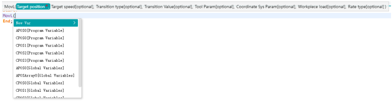
(6) For commands with multiple parameter combinations, such as movJ, movL, etc., various optional and mandatory parameters (parameters marked with red asterisk *) are included (although optional, the order of parameters for each parameter type is dependent). After entering each parameter, the editor updates the input prompt list for the available parameters and highlights all currently available parameters in the function prompt window. This approach efficiently guides users in editing commands with such parameter combinations.

On the PC software interface, there is a difference in how variables are displayed compared to the teach pendant programming UI. For example, when selecting a variable from the input prompt box and entering it in the editor, it should be displayed in the form of s:, p:, g:,or l: as a prefix. s: represents system variables, p: represents project variables, g: represents global variables, and l: represents program variables. To facilitate the filtering of variables from different domains, users can manually input s:, p:, g:, or l: to automatically update the input prompt box and display variables from the corresponding domain for selection.
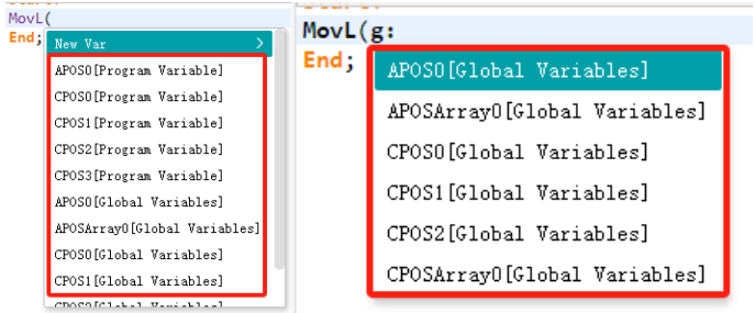
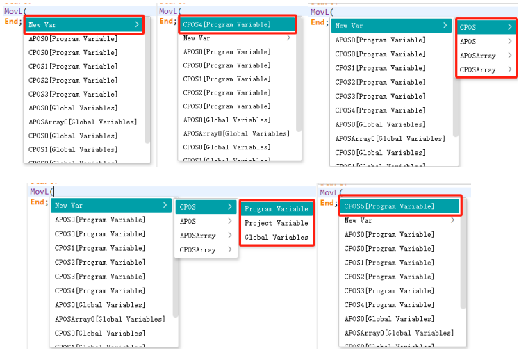
If the current parameter settings do not meet the requirements, variables can be added by selecting the option to add new variables. Clicking directly on "Add Variable" usually assigns a default initial value, for example, when using the MovL or MovJ instructions, the system will automatically generate the CPOS program variable. If you wish to create other types of variables, simply press the right arrow key (→) to display a diverse selection of variables. By default, these variables are classified as program variables. If you want to generate global variables or project variables, press the right arrow key (→) again, choose the desired variable, press Enter, and the variable will be successfully created and visually displayed at the current position.
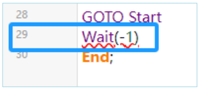
(7) The program editor can provide real-time error detection and display basic error messages while the user is typing. Error information is displayed in the compilation and debugging area below or highlighted in red on the error line for easy identification.

(8) Once the editing is complete, clicking the icon allows for the compilation and saving of the currently edited program. At this point, syntax errors are also checked. If any errors are displayed, the save operation will not be successful, and the user needs to make the necessary program modifications as prompted.
After verifying that there are no errors, the program can be successfully compiled and saved.
(9) Code comments can be added in the editing area using "// ".
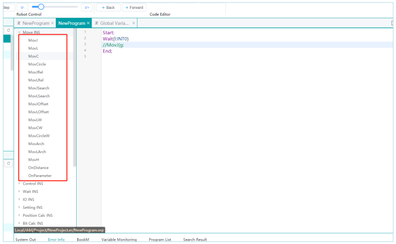
Double-clicking on the nodes in the expanded command list will display the corresponding commands.
Moving the cursor to the desired position in the editing area and double-clicking on the command will quickly add it to the program.

4.8.Display of Running Program
During single-step or continuous program execution, the currently running program line is highlighted.
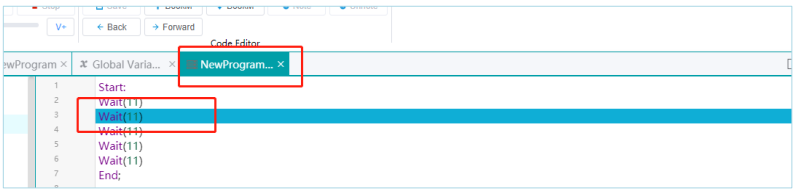
The virtual teach pendant can be opened during program execution to synchronize and compare the displayed pointer line for any differences.
4.9.Program Saving
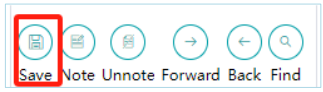
Click the icon in the toolbar to save the modified program locally.
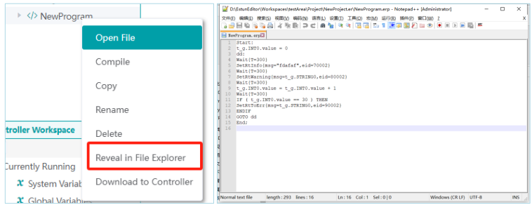
After the program save prompt is successful, you can right-click on the program and select "Reveal in File Explorer" to view the corresponding generated .erp file. In the file, t_g, t_p, and t_l respectively correspond to global variables, project variables, and program variables.
4.10.Workspace, Project and Program Upload/Download
This functionality requires a connection to the controller. Local programs can be downloaded to the controller, and controller programs can be uploaded to the local environment. It is also possible to selectively upload or download a node from the workspace tree. When clicking on a node in an independent workspace, it is important to ensure that the workspace exists either locally or on the controller; otherwise, an error will occur.
4.10.1. Download
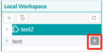
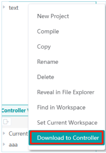
Select the local "text"→click the "Download" button
4.10.2.Upload
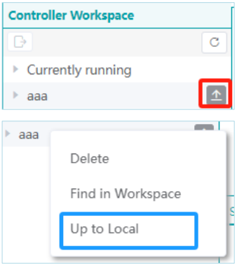
Select the "GlobalProg" on the server →Upload.
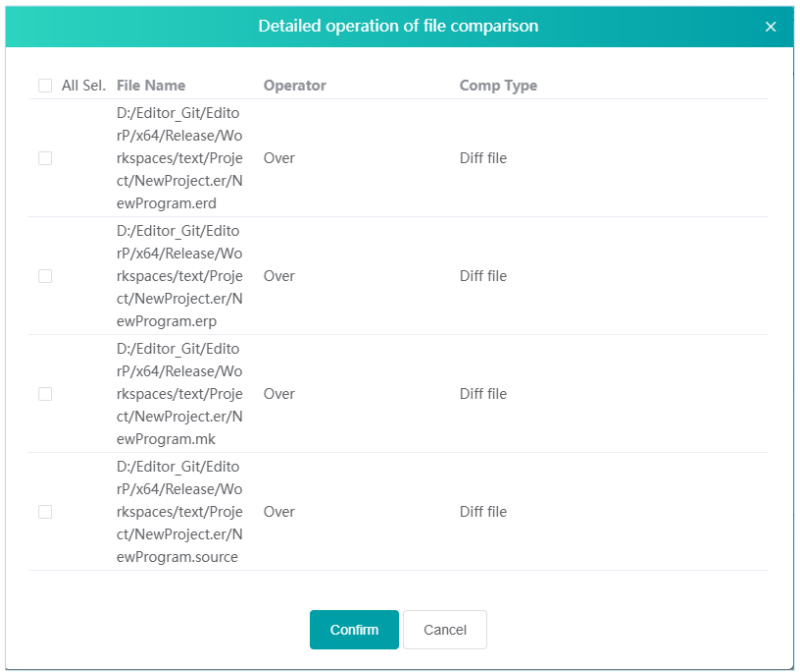
If there are differences between the local and controller versions, a prompt will appear, allowing the user to decide whether to overwrite the controller's file.
4.10.4.Upload/Download Error Messages
If an independent unit under the workspace is selected for upload/download and the workspace does not exist locally or on the controller, the following error will be reported.
(1) Download: If the workspace where the project resides does not exist on the server, the following error will be reported.

(2) Upload: If a project is selected from any workspace on the server, right-clicked, and then uploaded, and the corresponding workspace does not exist locally, the upload will fail, as shown in the following image

(2) Upload: If a project is selected from any workspace on the server, right-clicked, and then uploaded, and the corresponding workspace does not exist locally, the upload will fail, as shown in the following image.

4.10.5.Self-Triggered Program
In the controller workspace, select the specific program, and then open the program that needs to be set to start automatically.
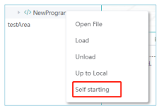
Once successfully configured, the software will display a prompt at the top indicating "Automatic startup program settings successful," and a corresponding icon will appear for the program within the interface.
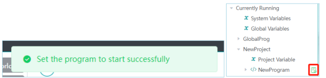
Please note that this configuration takes effect only within the “Currently Running”. Attempting to set automatic startup for applications in other workspaces will prompt the message 'Please set automatic startup programs in the current workspace'.

No comments to display
No comments to display