
9. 3D
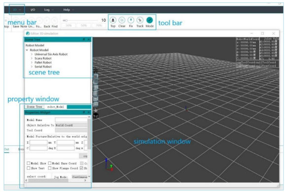
The 3D simulation includes the 3D menu, toolbar, property window, scene tree, and simulation window.
Left-click to rotate the scene, middle-click to pan the scene, and scroll the mouse wheel to zoom in or out.
9.1.Open the 3D Simulation Window
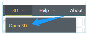
Click on "Open 3D Window" to load the 3D simulation window.
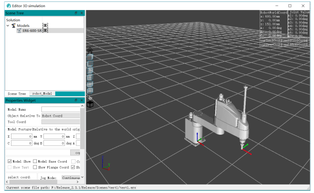
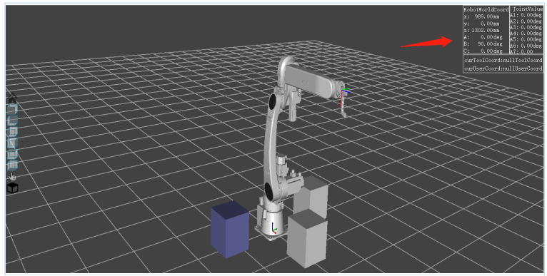
Note: The window data in the top right corner shows the robot's world coordinate system, which is the data relative to the center point of the robot's base surface.
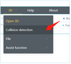
Click on "Collision Detection" to open the collision detection point list window. Further details on the collision detection module will be explained later.
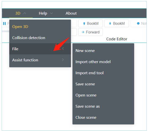
9.2.1.New Scene
(1) Prerequisite: If you only want to view the motion of a single robot without any scene, there is no need to create a new scene. However, if you want to include other models, you need to create a new scene. You can use the shortcut key CTRL+O.
(2) Click on the 3D menu -> Click on File -> Click on Create Scene to create a new scene, which includes creating a scene space and a scene file (or use shortcut key Crtl+N).
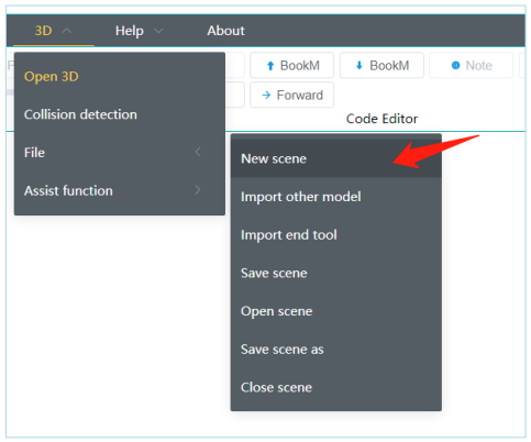
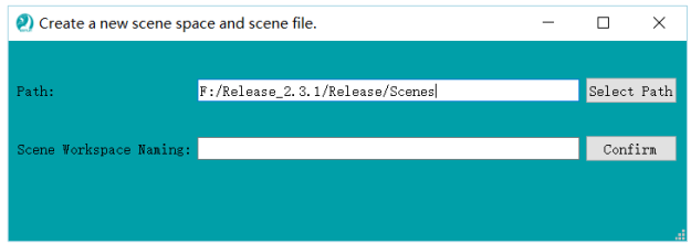
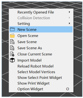
(3) Right-click on an empty space in the 3D simulation page and choose "Create Scene".
9.2.2.Import Other Models
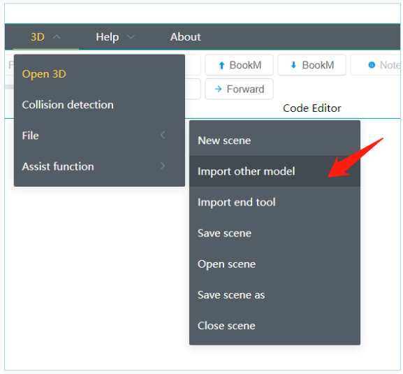
(1) Click on the 3D menu -> Click on File -> Click on Import Other Models to import models other than the robot model and robot tool model.
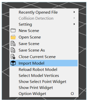
(2) Right-click on an empty space in the 3D simulation page and choose "Import Other Models".
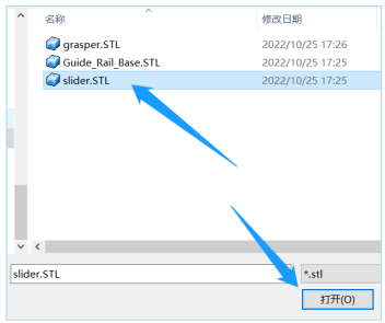
Note: Currently, the supported model format is .stl format. Please ensure that the size does not exceed 150MB. If the size exceeds 150MB, it may affect the smoothness of the display.
9.2.3.Import End Effector Tool Model
(1) Click on the 3D menu -> Click on File -> Click on End Effector Tool Model to import the model of the robot's tool.
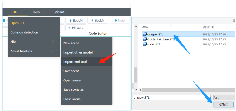
Note: Currently, the supported model format is .stl format. Please ensure that the size does not exceed 150MB. If the size exceeds 150MB, it may affect the smoothness of the display.
9.2.4.Save Scene
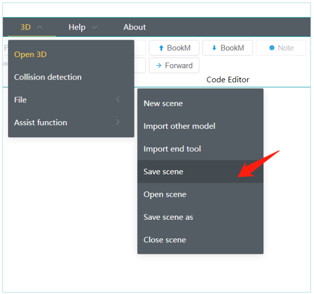
(1) Click on the 3D menu -> Click on File -> Click on Save Scene to save the current scene (Shortcut key (CTRL+S)) .
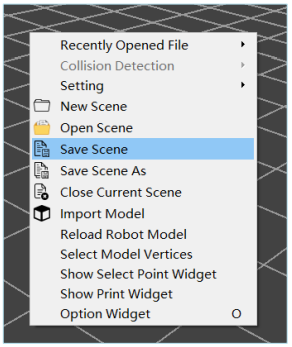
(2) Right-click on an empty space in the 3D simulation page and choose "Save Scene".
9.2.5.Open Scene
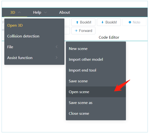
(1) Click on the 3D menu -> Click on File -> Click on Open Scene to open a 3D scene file (Shortcut key (CTRL+O)).
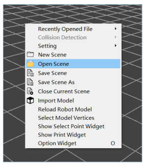
(2) Right-click on an empty space in the 3D simulation page and choose "Open Scene".
9.2.6.Save Scene As
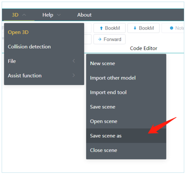
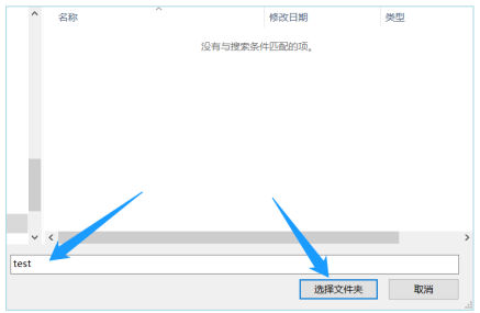
(1) Click on the 3D menu -> Click on File -> Click on Save Scene As to save the scene workspace files to a different folder
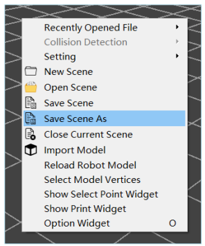
(2) Right-click on an empty space in the 3D simulation page and choose "Save Scene As".
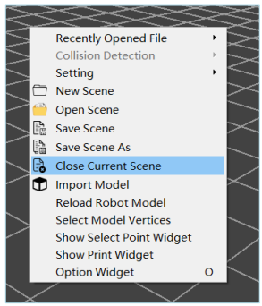
9.2.7.Close Scene
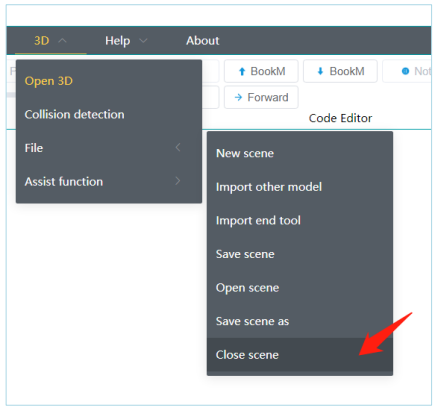
(1) Click on the 3D menu -> Click on File -> Click on Close Scene to close the currently opened scene.
(2) Right-click on an empty space in the 3D simulation page and choose "Close Current Scene".
9.3. "Accessibility" Menu
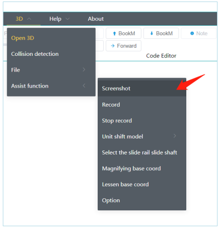
9.3.1. Capture Screen
Click on the 3D menu -> Click on Accessibility -> Click on Capture Screen to save a screenshot of the current simulation page.
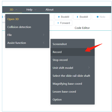
9.3.2.Record Screen
Click on the 3D menu -> Click on Accessibility -> Click on Record Screen to record a video of the current simulation page.
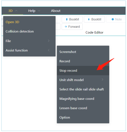
9.3.3.Stop Recording
Click on the 3D menu -> Click on Accessibility -> Click on Stop Recording to stop the current screen recording of the simulation page.
9.3.4.Unit Model Movement (ALT+1,2,3,4,5,6,7)
Click on the 3D menu -> Click on Accessibility -> Click on Unit Model Movement -> Choose XYZABC axis to move the model.
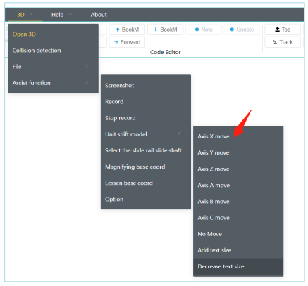
(1) Select X-axis: Corresponds to the translation axis X of the model. After selection, there will be text prompts in the scene. Press the UP arrow key on the keyboard to increase the value of the X-axis, and press the DOWN arrow key to decrease the value of the X-axis.(Shortcut key :ALT+1).
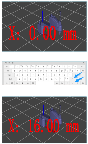
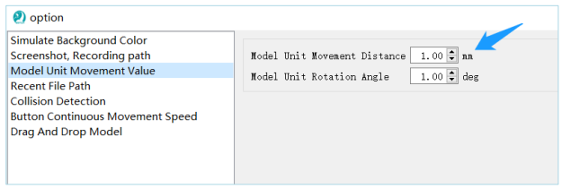
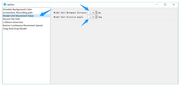
The default unit value added is 1, and you can set the unit movement length in the options.
(2) Select Y-axis: Corresponds to the translation axis Y of the model. After selection, there will be text prompts in the scene. Press UP arrow key on the keyboard to increase the value of the Y-axis ,and press the DOWN arrow key to decrease the value of the Y-axis(Shortcut key : ALT+2).
(3) Select Z-axis: Corresponds to the translation axis Z of the model. After selection, there will be text prompts in the scene. Press UP arrow key on the keyboard to increase the value of the Z-axis ,and press the DOWN arrow key to decrease the value of the Z-axis(Shortcut key : ALT+3).
(4) Select A-axis: Corresponds to the rotation axis A of the model. After selection, there will be text prompts in the scene. Press UP arrow key on the keyboard to increase the value of the A-axis, and press the DOWN arrow key to decrease the value of the A-axis(Shortcut key : ALT+4).
(5) Select B-axis: Corresponds to the rotation axis B of the model. After selection, there will be text prompts in the scene. Press up arrow key on the keyboard to increase the value of the B-axis, and press the DOWN arrow key to decrease the value of the B-axis (Shortcut key : ALT+5).
(6) Select C-axis: Corresponds to the rotation axis C of the model. After selection, there will be text prompts in the scene. Press UP arrow key on the keyboard to increase the value of the C-axis, and press the DOWN arrow key to decrease the value of the C-axis (Shortcut key: ALT+6).
(7) Select "No Movement" axis: Cancel the movement axis of the model (Shortcut key: ALT+7).
(8) Click on "Increase Text Size": Enlarges the text of the model's movement axis (Shortcut key: ALT+E).
(9) Select "Decrease Text Size": Reduces the text size of the model's movement axis (Shortcut key: ALT+R).
9.3.5.Select Slider Axis
Click on the 3D menu -> Click on Accessibility -> Click on Slider Axis
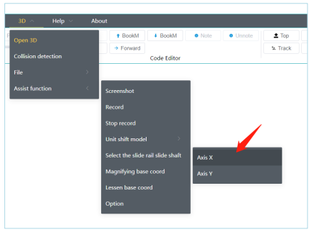
(1) Selecting the X-axis means that both the slider and the slider robot will move in the X-axis direction of the simulation world coordinate system.
(2) Selecting the Y-axis means that both the slider and the slider robot will move in the Y-axis direction of the simulation world coordinate system.
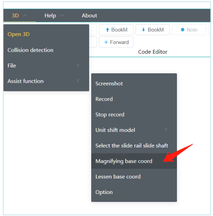
9.3.6.Zoom In Base Coordinates
Click on the 3D menu -> Click on Accessibility -> Click on Zoom In Base Coordinates to zoom in on the base coordinates of the current model (Shortcut key: Page Up).
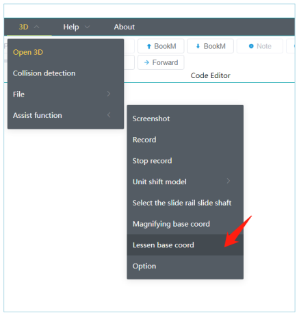
9.3.7.Zoom Out Base Coordinates
Click on the 3D menu -> Click on Accessibility -> Click on Zoom Out Base Coordinates to zoom out of the base coordinates of the current model (Shortcut key: Page Down).
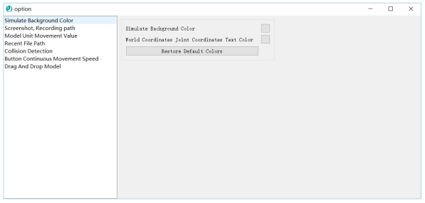
9.3.8.Options
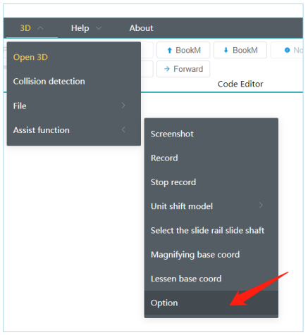
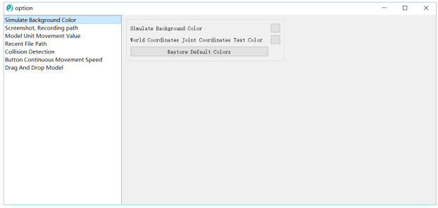
(1) Set simulation background color and text color in the data window.
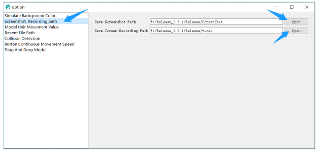
(2) Open the folder for saving screenshots and recorded screens.
(3) Set the value for unit movement of the model
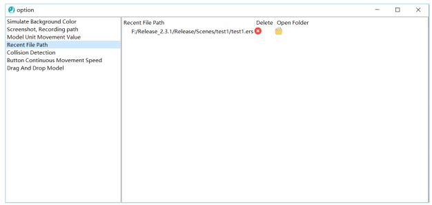
(4) Recent file paths, Manage the recently opened file paths. Click  to delete a file path record, and click
 to open the folder of this path.
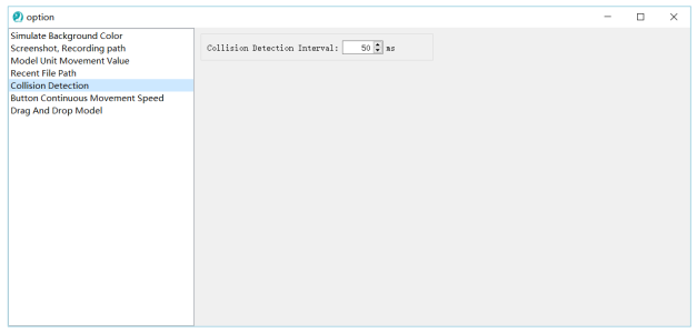
(5) Collision Detection,Set this parameter to adjust the time interval for collecting collision points in collision detection.
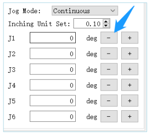
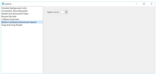
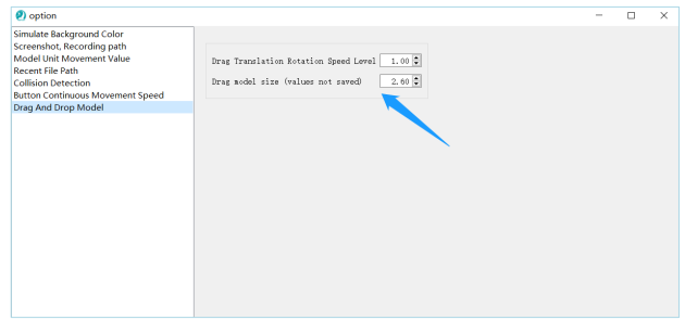
(7) Dragging Model,Set the speed of dragging the model and the size of the coordinate system for dragging the model.
9.4.Toolbar
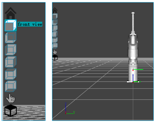
9.4.1.Front View
To set the front view of simulation window.
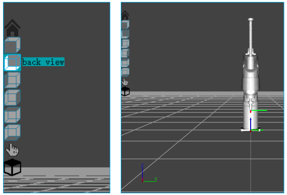
9.4.2.Back View
To set the rear view of simulation window.
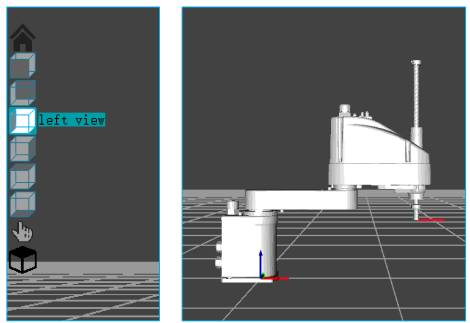
9.4.3.Left View
To set the left view of simulation window
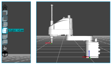
9.4.4.Right View
To set the right view of simulation window.
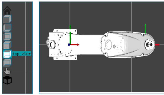
9.4.5.Top View
To set the top view of simulation window
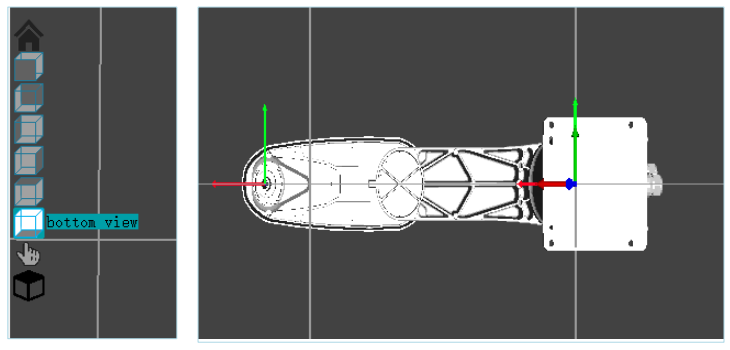
9.4.6.Bottom View
To set the bottom view of simulation window.
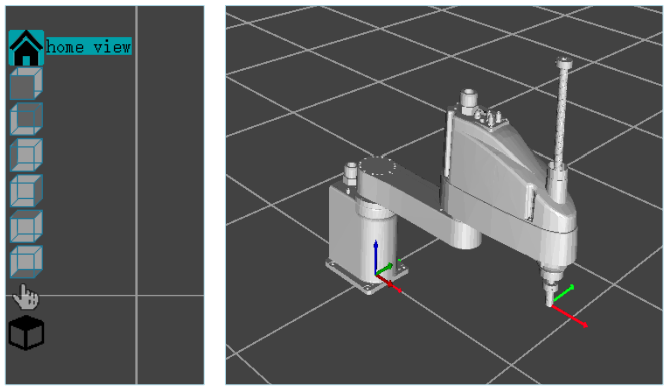
9.4.7.Restore View
To set the restore view of simulation window.
9.4.8.Path
To set the path of simulation window
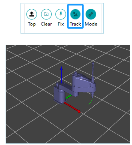
Note: This path is relative to the center point of the robot base. Therefore, in the case of a 7th-axis slider simulation, the displayed path is only for the robot and does not include the path of the slider.
9.4.9.Always On Top
To set the simulation window to be always on top
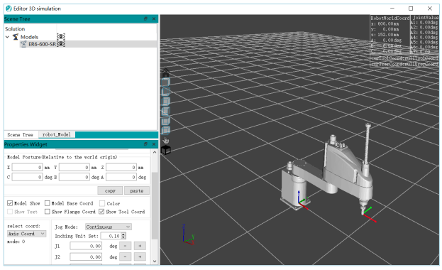
9.4.10.Modes
Opens or closes the scene tree and property window in the simulation window.
9.4.11.Clear
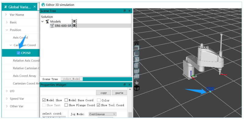
Clears the display of all selected variables in the 3D simulation of the current project. Currently, the variables that can be displayed in 3D include position variables: axis coordinates (APOS) and Cartesian coordinates (CPOS), area variables (AEAR), user coordinates (USERCOOR), and tool center point coordinates (TOOL).
Example: After selecting variables in the project, they are displayed in the 3D simulation.
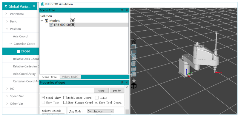
Clicking the Clear button will remove all variables that are currently displayed in the 3D simulation.
9.4.12.Drag
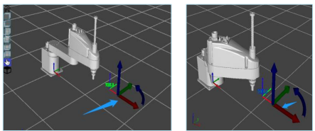
The dragging mode is displayed at the end current robot's tool coordinate system, allowing you to perform virtual robot axis dragging movements.
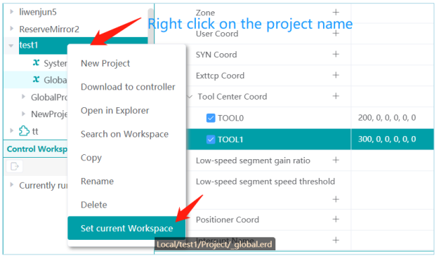
First, set the project as the current project: Right-click on the project name and select "Set as Current Project Space".
In the Property Window, select the current tool coordinate system.
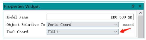
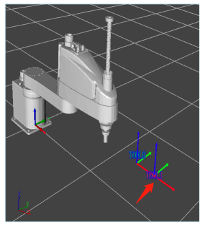
Click on "Drag".
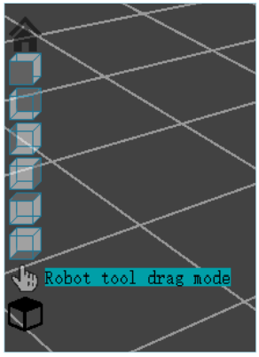
A dragging model will appear at the end of the robot's tool. Place the mouse over the corresponding axis and drag it along the axis.
9.4.13.One-Click Fixing
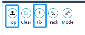
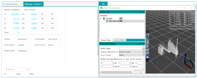
Fixes the 3D simulation window in the split-screen position. After opening the 3D window, click on "Always On Top" first, and then click on "One-Click Fixing".
9.4.14.Model Dragging
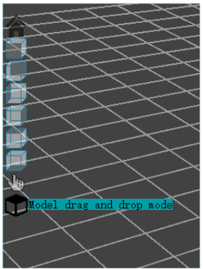
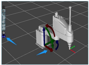
After selecting a model, click on the "Drag Model" button. A coordinate system will appear, and you can manually move the model by dragging the coordinate system.
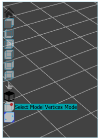
9.4.15.Select Model Vertices Mode
Activate the vertex selection mode, click on the model, and you can select the vertices of the model.
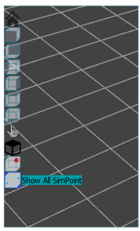
9.4.16. Show All SimPoint
The default is to start displaying all simulation points. Click to cancel displaying all simulation points to hide the newly created simulation points in 3D.
9.5. Property Window
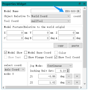
9.5.1.Model Name
To display current model's name.
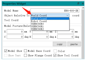
9.5.2.Set Current Reference Coordinate System
When in the selection point mode, the coordinate data of the simulation points will change according to the data of the reference coordinate system. Here, you can set the reference coordinate system.
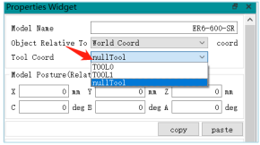
9.5.3.Set Current Robot Tool Coordinate System
To select the current virtual robot's end-of-arm tool coordinate system.
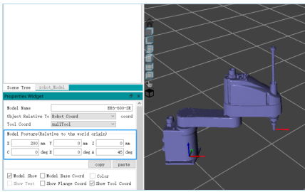
9.5.4.Set Model Posture
To set the current model's posture in the current simulation scene.
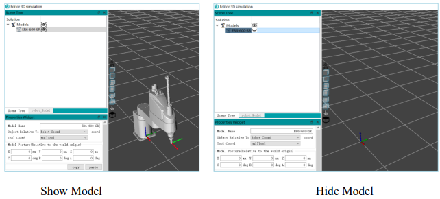
9.5.5.Set Model Display and Hide
To set the visibility of the model in the simulation page.
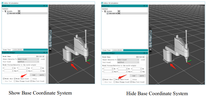
9.5.6.Set Base Coordinate System Display and Hide
To set the visibility of the model's base coordinate system in the simulation page.
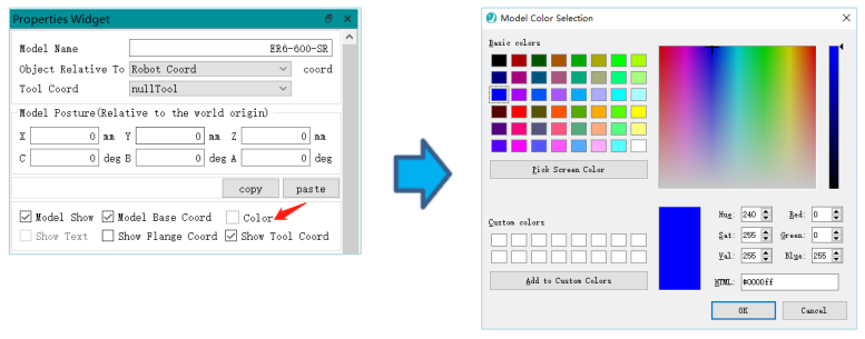
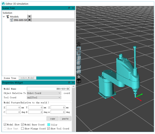
9.5.7.Set Model Color
To set the model's color. Click on the Color button and select a color.
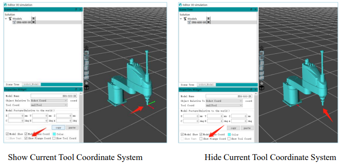
9.5.8.Set Robot Flange Coordinate System Display and Hide
To set the visibility of the robot's flange coordinate system in the simulation page.
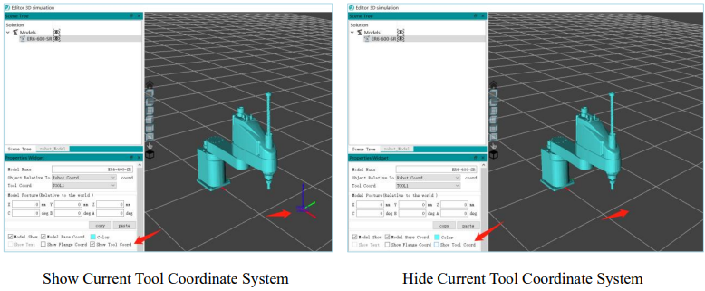
9.5.9.Set Robot Tool Coordinate System Display and Hide
To set the visibility of the robot's tool coordinate system in the simulation page.
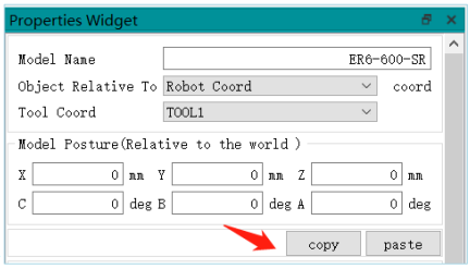
9.5.10.Copy Model Posture
To copy the posture data of the current model.
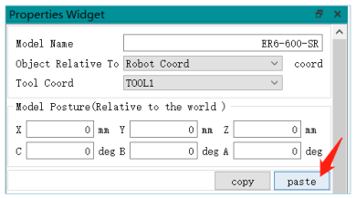
9.5.11.Paste Model Posture
To paste the copied pose data to the current model.
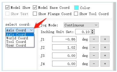
9.5.12.Select Virtual Robot Motion Reference Coordinate System
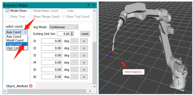
To specify the coordinate system that the virtual robot uses as a reference for motion. The default initialization is the axis coordinate system.
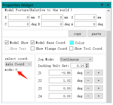
9.5.13. Display Current "mode" Value of Virtual Robot
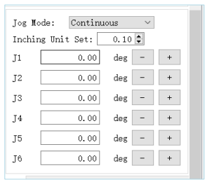
9.5.14.Single Axis Control of Virtual Robot
Based on the chosen coordinate system, the axis control buttons will switch between various axis control modes. The initial setting is the axis coordinate system, and axis control facilitates continuous movement.
9.6.Scene Tree
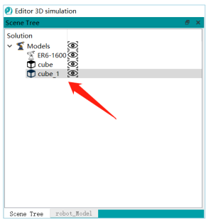
9.6.1.Model List
To list the models in the scene. The model name is on the left, and the control for showing or hiding the model is on the right.
The first row of "Models" controls the visibility of all models in the current scene.
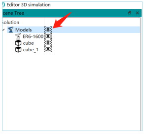
9.6.2.Right-Click on "Models" to Open the Current Scene Space Folder
Right-click on "Models" to open the current scene space folder.
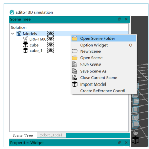
9.6.3.Right-Click Menu for Scene Tree Model Item
(1) Right click on the robot model menu
Right-clicking on a model item in the scene tree opens a menu. If the model is a robot, the menu options are the same as those in "9.7.4. Right-Click Robot Model Menu". For specific details, refer to "9.7.4. RightClick Robot Model Menu".
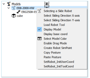
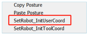
⚫ Click to set the robot to initialize the user coordinate system :Set the current robot user coordinate system to the default value XYZABC (0,0,0,0,0,0,0)
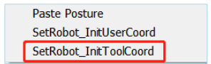
⚫ Click to set the robot initialization tool coordinate system: Set the current robot tool coordinate system to the default value XYZABC (0,0,0,0,0,0,0).
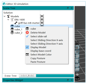
(2) Right click on the regular model menu
If the model is a regular model, a menu will pop up with options. The functionality of the menu options with the same names as in "9.7.5. Right-Click Model Menu" is the same. For specific details, refer to "9.7.5. RightClick Model Menu".
(3) Right click on the tool model menu
If the model is a robot end-of-arm tool model, a menu will pop up with options. The functionality of the menu options with the same names as in "9.7.6. Right-Click Tool Model Menu" is the same. For specific details, refer to "9.7.6. Right-Click Tool Model Menu".
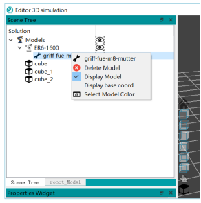
(4) Right click on the reference coordinate system model menu
Right-click on the reference coordinate system and click on Convert Reference Coordinate System to User Coordinate System to convert the current reference coordinate system to a user coordinate system with the robot base center coordinate system as the parent node. Icon by  to
 .
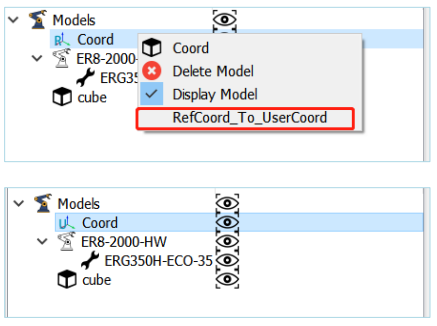
(5) Right click on the user coordinate system model menu
Right click on the user coordinate system
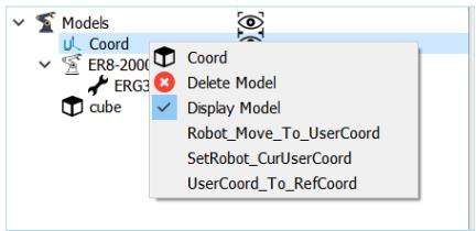
⚫ Click on the robot to move to the user coordinate system: Click on the robot to move to the user coordinate system, and the robot will move to that user coordinate system using the current tool coordinate system.
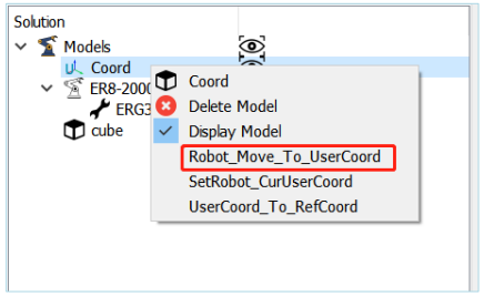
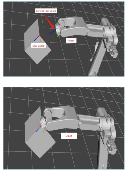
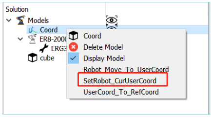
⚫ Click to set the robot's current user coordinate system: Click to set the current user coordinate system of the robot, and the robot will use the current user coordinate system as the user coordinate system.
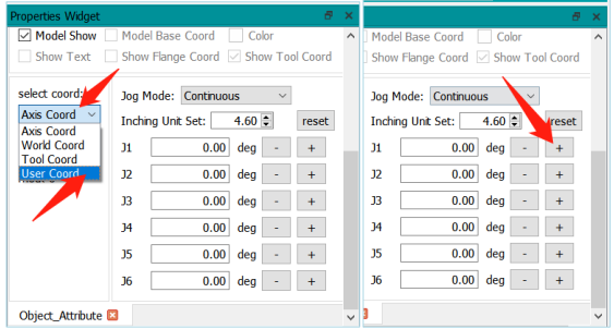
⚫ Click on the user coordinate system to convert to a reference coordinate system: Clicking on the user coordinate system to reference coordinate system can convert the user coordinate system to a reference coordinate system. Icon by  to
 .
(6) New Tool Coordinate System
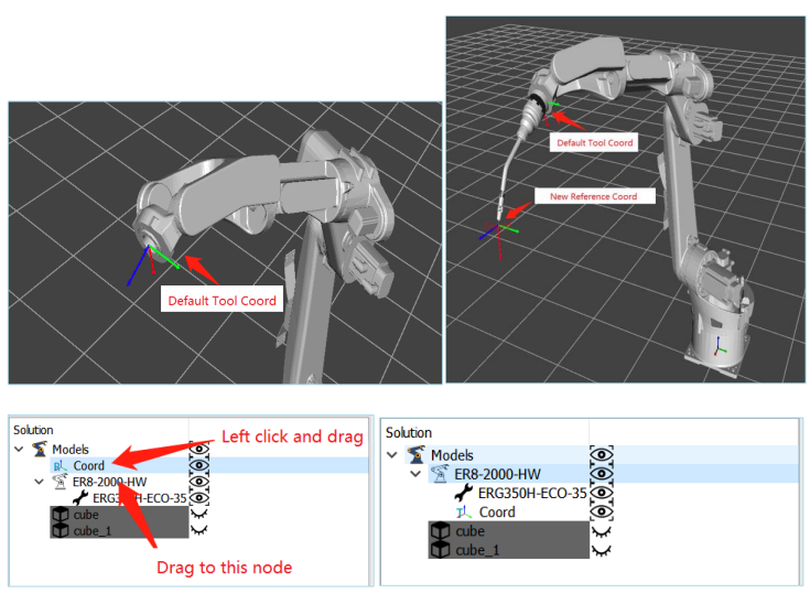
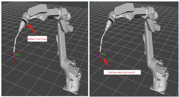
The newly created reference coordinate system or user coordinate system can be transformed into the robot's tool coordinate system by dragging it under the robot node.
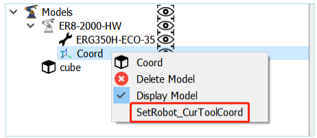
(7) Right click on the tool coordinate system menu
Click to set the robot's current tool coordinate system: Click to set the current robot tool coordinate system as the current tool coordinate system
9.7.Simulation Window
9.7.1.Simulation Window
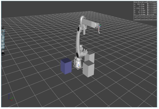
The  at bottom-left corner represents the pose of the world coordinate system.
9.7.2.Robot Data Window
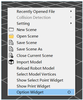
9.7.3.Right-Click Menu for Simulation Scene Window
(1) Recently Opened Scene Files Menu
Records the recently opened scene files for quick selection.
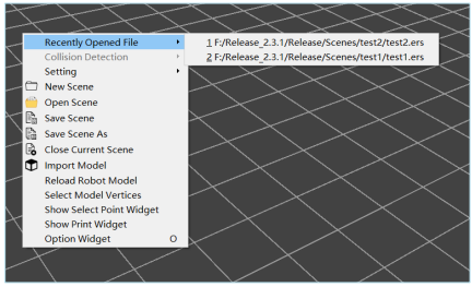
(2) Collision Detection
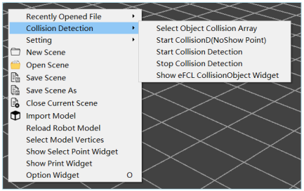
⚫ Select Object Collision Sets
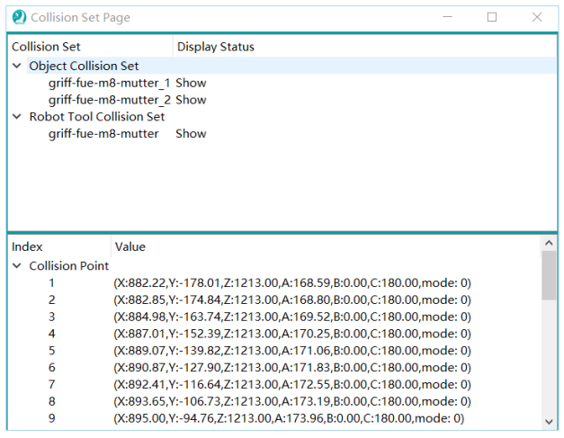
To select the object collision sets, which are the models to be included in the collision detection. When clicking this option, a collision set page will appear as shown in the figure. The collision sets are divided into object collision sets and robot tool collision sets. The object collision sets include regular models that need to participate in collision detection, excluding the models related to the robot. The robot tool collision sets include the tool models that the robot needs to participate in collision detection.
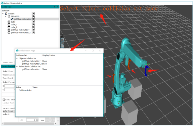
To select models for collision detection, simply click on them. When selecting regular models, they will appear in orange-red color, and when selecting tool models, they will appear in dark blue.
Additionally, joint models on the robot (such as pallet models or other balance bar models, which are not currently included in collision detection) are automatically included in the collision detection.
The top half of the collision set page displays the names of the currently selected models for collision detection and their display status.
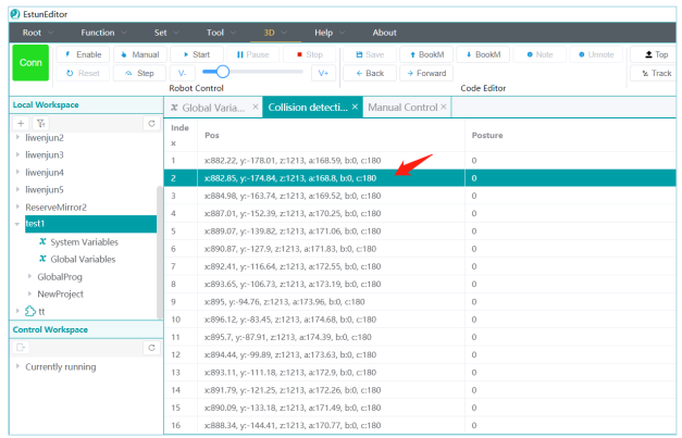
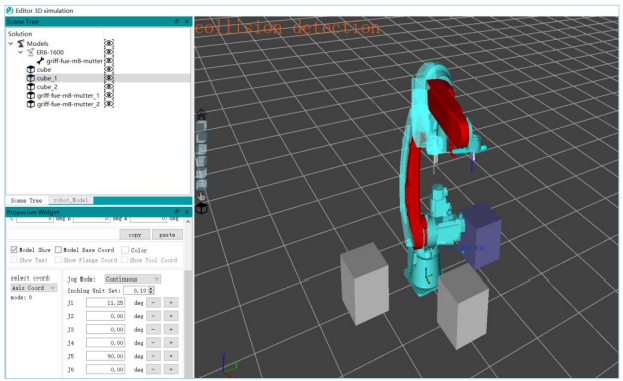
The bottom half is used for collecting collision points after activating the "Start Collision Detection" function, enabling the collection of collision points at regular intervals. By clicking on the collected collision points, it is possible to quickly navigate the virtual robot and examine the collision situation.
⚫ Start Collision Detection (Without Recording Collision Points)
Clicking this function starts the collision detection thread, which performs collision detection on the models in the collision set. During the movement of the virtual robot, if there is a collision with any model in the collision set, the model will turn red as shown in the figure. To activate the "Start Collision Detection" function, you need to click on the "Stop Collision Detection" function.
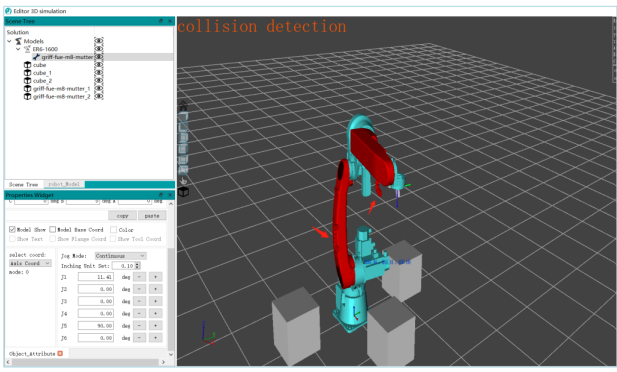
⚫ Start Collision Detection
Clicking this function starts the collision detection thread, which performs collision detection on the models in the collision set. During the movement of the virtual robot, if there is a collision with any model in the collision set, the model will turn red. Additionally, while moving the robot, the system will periodically check and record collision points at the locations of collisions, as shown in the figure.
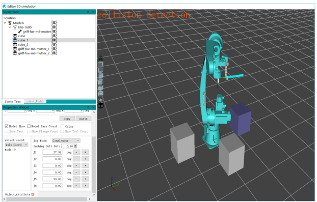
By clicking on the recorded collision points on the collision detection page, it is possible to quickly move the robot to the collision points and examine the collision detection situation.
⚫ Stop Collision Detection
Stops the collision detection thread.
⚫ Display Collision Detection Set Window
If the collision detection set window is closed, clicking this function will reopen the selected model collision set.
(3) Settings
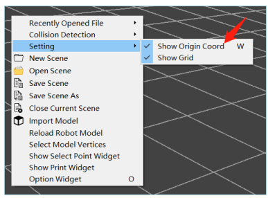
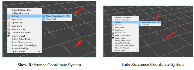
Display Reference Coordinate System: Clicking this function will show or hide the reference coordinate system model.
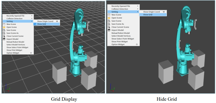
Grid Display: Clicking this function will show or hide the grid.
The functionality of opening and closing scenes is the same as the corresponding tools in the "File" menu in section 9.2. Please refer to the functionality of the corresponding tools in the "File" menu in section 9.2. This is provided for ease of use.
(4) Reload Connected Robot
This function is used when, in the connected state, clicking on close scene will also close the robot model.
If you want to display the current robot model again without switching to another robot model, you can click this function.
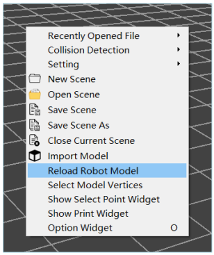
(5) Select Point Mode
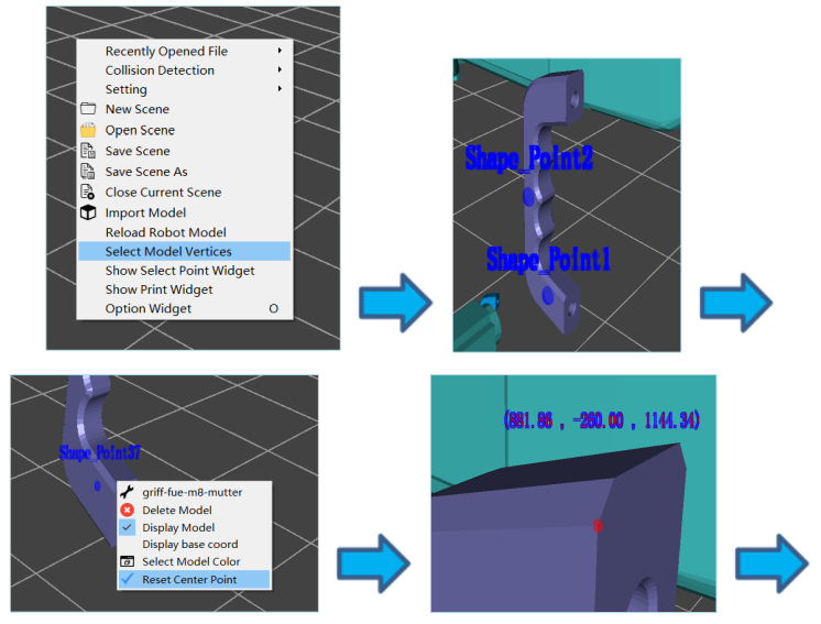
Enables the selection of model vertices to quickly create vertices on the model, making it convenient to move the robot end-of-arm tool to that vertex for adjustment of point data. When selecting point mode, you need to click on the model to be selected, then right-click on the model and select the "Reset Center Point" function. Then zoom in on the model and select the vertices of the model. When the color of the mouse's sphere turns red, it means that the point is a vertex of the model. Use ALT + S + left-click to create a simulation point for the model vertex.
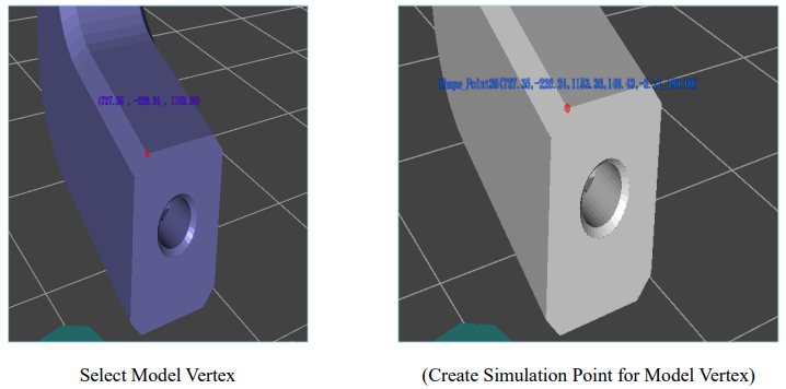
(6) Display Select Point Window
Clicking this function opens the select point page, which records the selected simulation points or the midpoints and centers created based on simulation points. Please refer to section 9.9 for information on how to create simulation points.
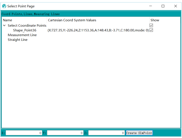
(7) Information Output Window
Clicking this function opens or closes the information output window. This is used to view debugging, warning, or alarm information in the 3D simulation.
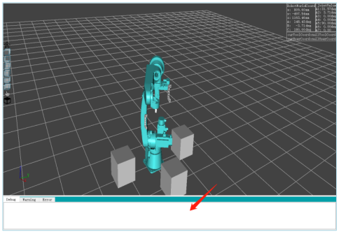
(8) Options
Clicking this function opens the options window.
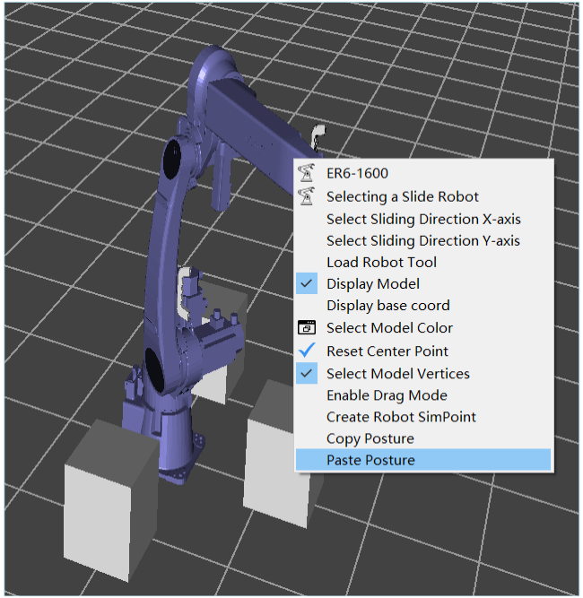
9.7.4.Right-Click Robot Model Menu
Right-clicking on the model will bring up a menu that allows you to set the model's properties.
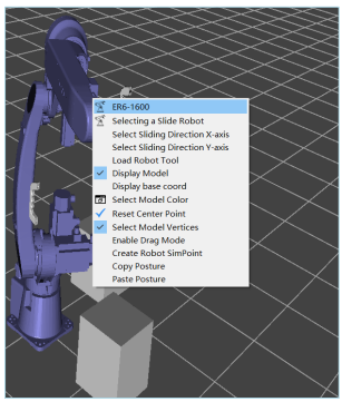
(1) Robot Model Name
Displays only the name, no effect if clicking.
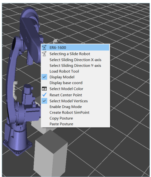
(2) Select Robot Model on Slider
Clicking this option allows you to select the robot model on the slider.
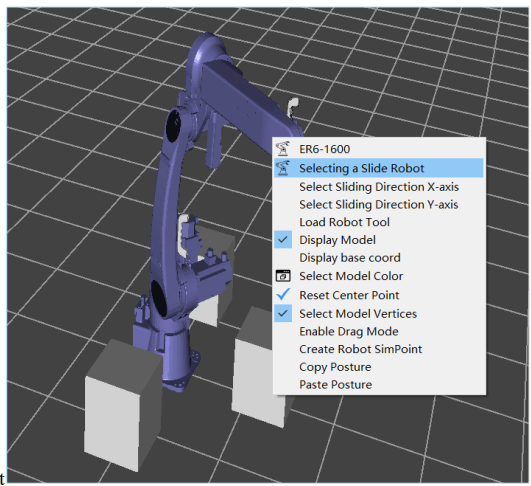
(3) Select X-axis Movement on Slider for the Robot
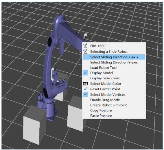
(4) Select Y-axis Movement on Slider for the Robot
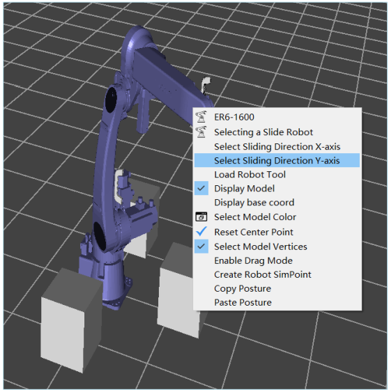
(5) Import Robot End-of-Arm Tool Model
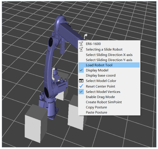
(6) Show Robot Model
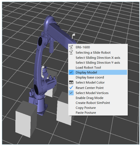
(7) Select Robot Base Coordinate System
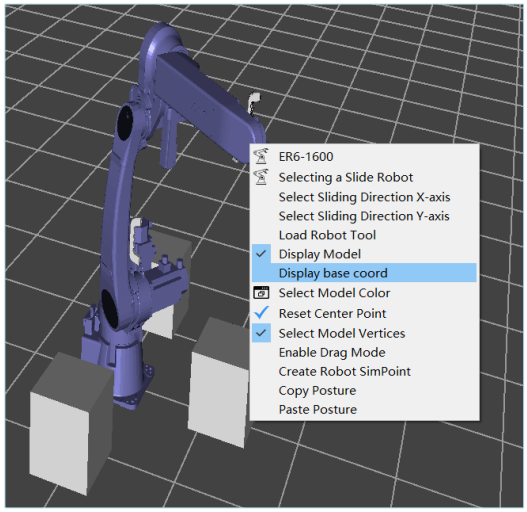
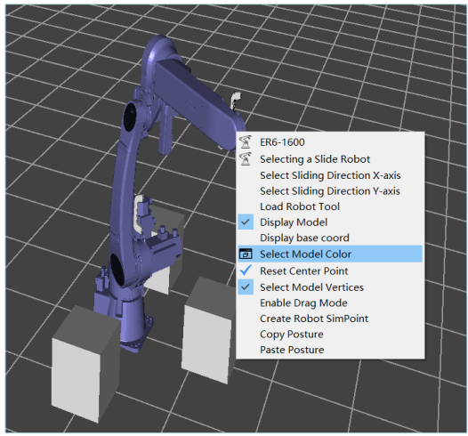
(8) Select Robot Model Color
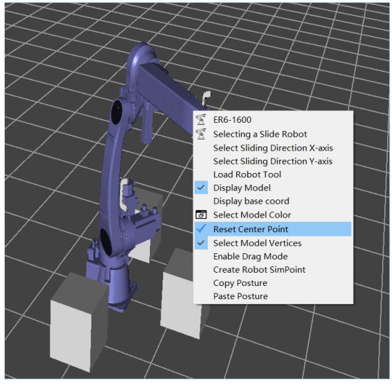
(9) Reset Center Point
To set the rotation and zoom center position of the scene to the location clicked by the mouse. This position is initially set to the center position (0,0,0) of the world coordinate system.
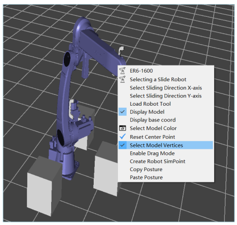
(10) Select Point Mode
Enabling this mode allows you to select vertices on models other than the robot model. When the mouse moves over the vertices of a model, the color of the current mouse sphere turns red. Use CTRL + left-click to create a simulation point relative to the reference coordinate system at the vertex position on the model. The default reference coordinate system is the world coordinate system.
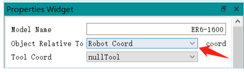
The reference coordinate system can be set to the world coordinate system, robot coordinate system, or other user-defined coordinate systems.
Creating simulation points allows you to quickly move the robot end tool to that simulation point or create CPOS variable points.
Note: The robot will move to the simulation point with the current posture. Similarly, when creating a CPOS variable point, it is based on the XYZ values of that simulation point and the robot's current posture values. If there is a requirement for posture, the robot needs to be moved to that point, and then the robot's posture values should be adjusted for teaching
(11) Select Drag Mode
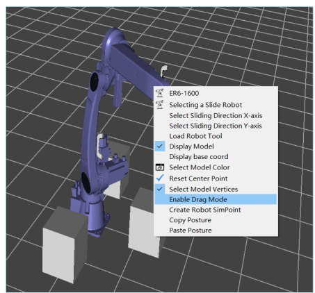
Enabling this mode will display the drag model under the current tool coordinate system variable of the robot. It includes XYZABC six-axis models. When you click and drag this model on the robot, it represents singleaxis movement of the robot based on the tool coordinate system as the reference coordinate system.
(12) Create Tool End Simulation Point
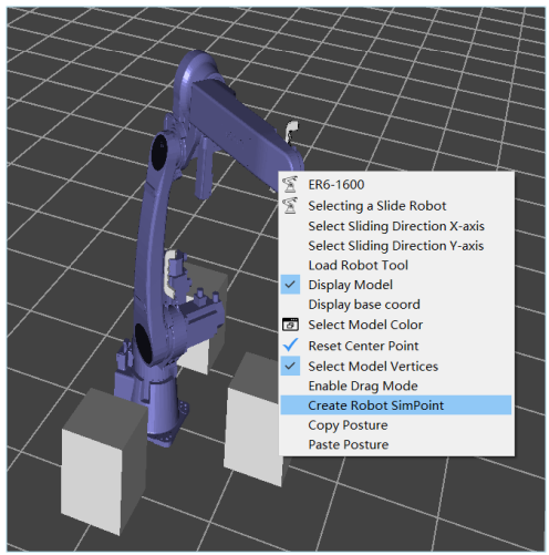
Using the robot coordinate system as the reference coordinate system and under the current tool variable of the robot, you can create simulation points for the robot's end-of-arm tool variable.
This is used to record points that may be needed or to quickly move the robot between such points.
(13) Copy Posture
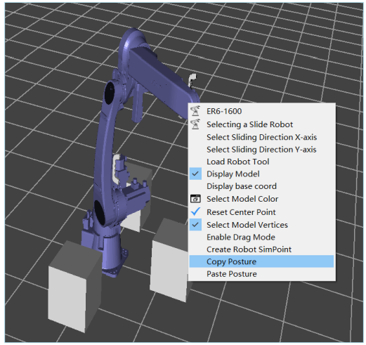
The copy posture and paste posture functions are used together. Clicking this function will copy the posture data of the current model
(14) Paste Posture
Pasting the posture copies the saved pose data of another model and pastes it into the target model to apply it, allowing for quick placement of models and scene setup.
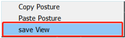
(15) save View
Right click on the menu and click Save View to save the current camera view to a temporary list.
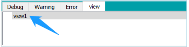
Double click on the temporary list to return to the camera position of the saved view.
9.7.5.Right-Click General Model Menu
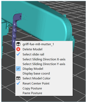
(1) Model Name
The first column in the menu displays the model name.
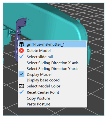
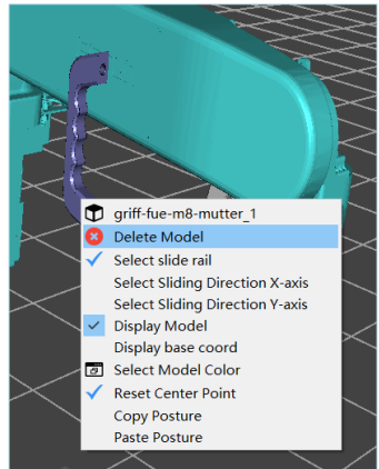
(2) Delete Model
Clicking this function will delete the model
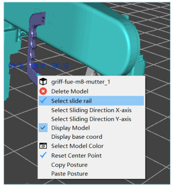
(3) Select Slider
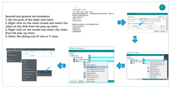
Click this function to set the model as a slider model. It is used for setting up the seventh-axis ground track model.
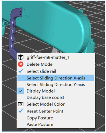
(4) Select X-axis Slide Direction
By clicking on this function, the motion direction of the rail model, which has already been configured, can be set to either the X-axis or the Y-axis.
(5) Select Y-axis Slide Direction
By clicking on this function, the motion direction of the rail model, which has already been configured, can be set to either the X-axis or the Y-axis.
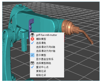
(6) Show Model
Clicking this function will show or hide the model.
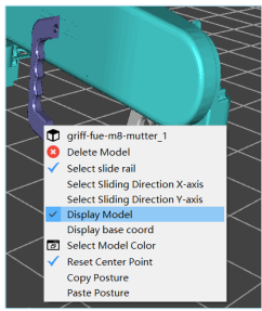
(7) Show Base Coordinate System
Clicking this function will show or hide the base coordinate system of the model.
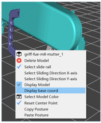
(8) Select Model Color
Clicking this function allows you to set the color of the model.
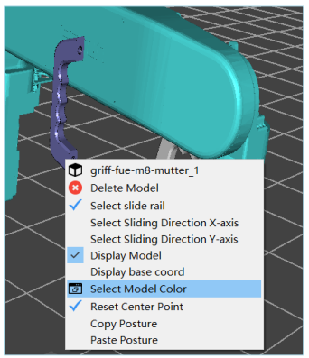
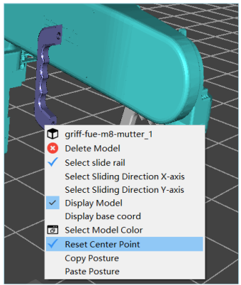
(9) Reset Center Point
Clicking this function allows you to set the current mouse position as the center point for rotation and zooming.
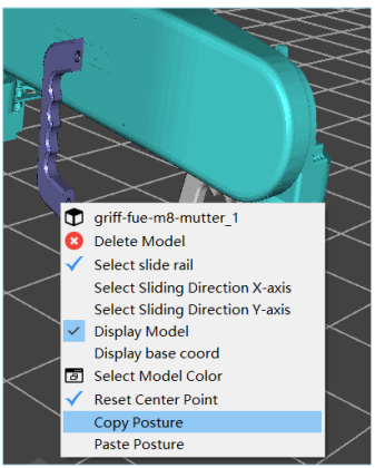
(10) Copy Posture
Clicking on this function allows the current posture data of the model to be copied.
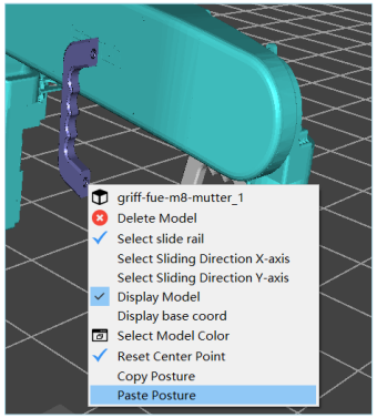
(11) Paste Posture
Clicking on this function allows the current posture data to be pasted onto the current model, enabling quick placement of the model.
(12) Save View
Right click on the menu and click Save View to save the current camera view to a temporary list.
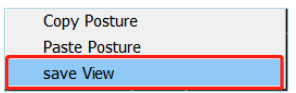
Double click on the temporary list to return to the camera position of the saved view.
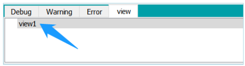
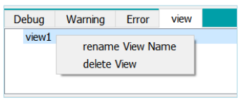
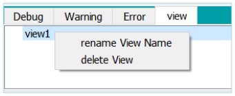
Right click on the current view list to rename or delete the view.
9.7.6.Right-click on the Tool Model Menu
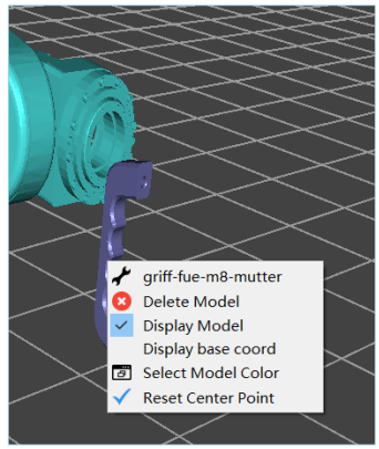
(1) Model Name
The first column of the menu displays the model name.
(2) Delete Model
Clicking on this function deletes the model.
(3) Show Model
Clicking on this function shows or hides the model.
(4) Show Base Coordinate System
Clicking on this function shows or hides the base coordinate system of the model.
(5) Select Model Color
Clicking on this function allows setting the model color.
(6) Reset Center Point
Clicking on this function sets the current mouse position as the center point for rotation, zooming in, and zooming out.
(7) save View
Right click on the menu and click Save View to save the current camera view to a temporary list.
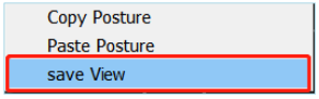
Double click on the temporary list to return to the camera position of the saved view.
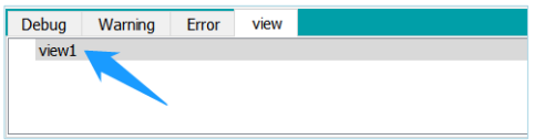
Right click on the current view list to rename or delete the view.
9.7.7.Right-click on the Point Model Menu
When right-clicking on the point model, a menu will pop up.
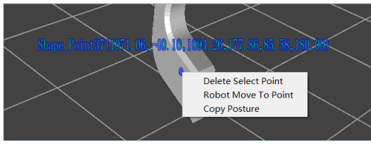
(1) Delete Selected Point
Clicking on this function deletes the current simulation point.
(2) Create Reference Coord
You can create a new standard reference coordinate system at this point and the Set Coordinate System window will appear.
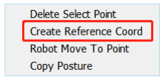
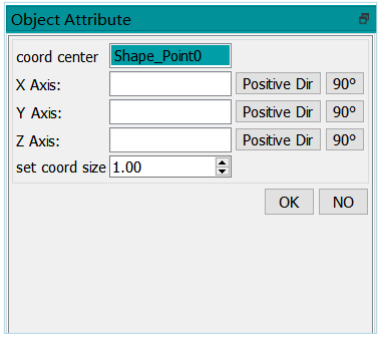
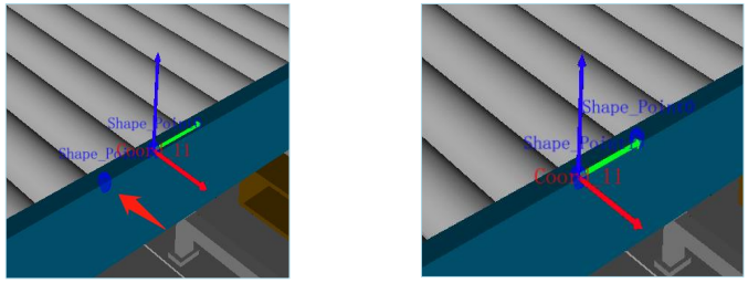
The center point of the coordinate system displays the name of the current point. When this option is selected, left click on different points to move the coordinate system.
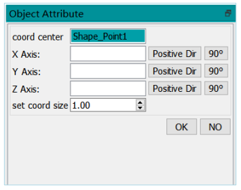
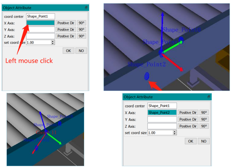
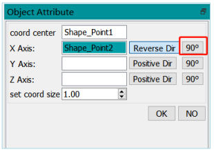
When clicking on the X-axis selection box in the Coordinate System Settings window, the orientation of the X-axis is selected. After clicking this option, clicking on the point position will show the change in orientation of the X-axis. The principle of the Y-axis is the same as that of the Z-axis.
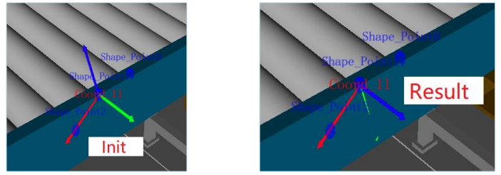
The direction is based on the current axis as the rotation axis and the rotation angle. Positive direction button  ,following the right-handed coordinate system, the direction of the current axis arrow is used as the direction of thumb pointing, while the direction of other fingers bending is the direction of coordinate system rotation. Taking the X-axis as an example.y
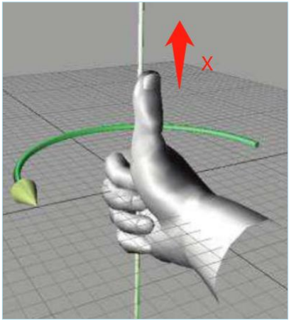
When you click on the image shown below:
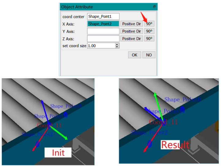
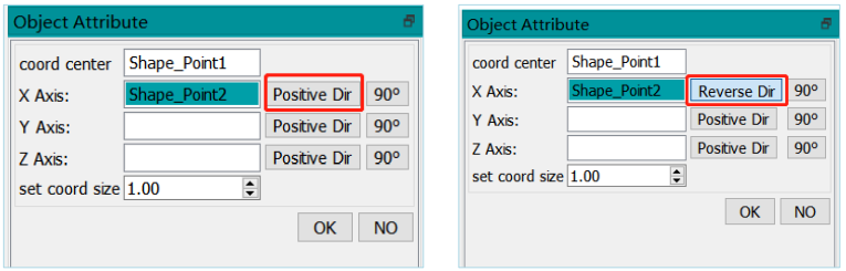
Click the forward direction button to change direction.
Click the 90 degree button, which is opposite to the direction of rotation in the positive direction.
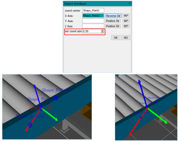
Setting the size of the coordinate system allows you to set the size of the current newly created coordinate system.
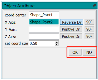
(3) Move Robot to Selected Point
Clicking on this function quickly moves the robot's current tool coordinate system end position to that point.
The posture data is the current robot's posture data. The robot may not be able to move to any position, depending on whether the point's data is within the robot's inverse solution range.
(4) Copy Posture
Clicking on this function copies the posture data of this point.
9.8.External Axis (Ground Track Axis) Simulation
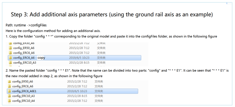
9.8.1.Configure the Robot's Config File
9.8.2.Build the Scene
(1) Create a new scene.
(2) Select the robot model.
(3) Import the slider and rail base models.
Note: The world origin coordinate system for the SolidWorks base and slider models should be set to the bottom-left corner.
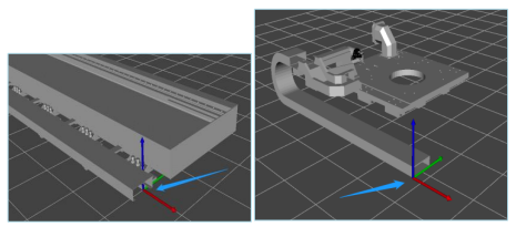
(4) Obtain the coordinates of the slider relative to the base origin using SolidWorks.
(5) Obtain the coordinates of the center point of the robot base surface relative to the slider base origin using SolidWorks.
(6) Manually record the data in a text file and input the data into the corresponding model's posture. Set the translation direction for the slider and rail robot.
9.9. Create Simulation Points
9.9.1.Create Arbitrary Simulation Points for Models
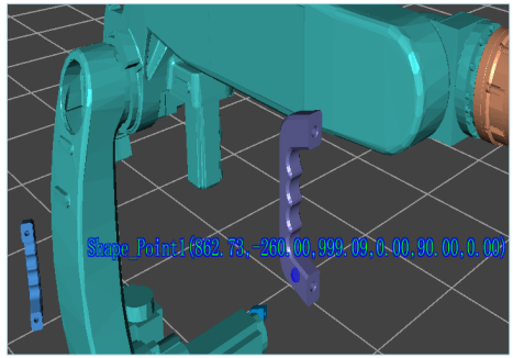
Move the mouse over the model to the desired position for creating a new simulation point, then press CTRL + left-click to create an arbitrary simulation point.
Arbitrary simulation points are displayed in blue color as shown in the figure.
9.9.2.Create Vertex Simulation Points for Models
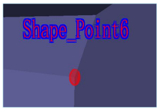
Tight-click on the blank area of the simulation window to open the menu, select "Select Point Mode", and enable it. Click on the desired model, then right-click on the model to open the menu and select "Reset Center Point". The mouse pointer and the text will turn red, indicating the model's vertex. Press CTRL + left-click to create a vertex simulation point. After using the point selection mode, click on "Select Point Mode " again to disable it for smooth 3D simulation operation.
9.9.3.Select Point Window
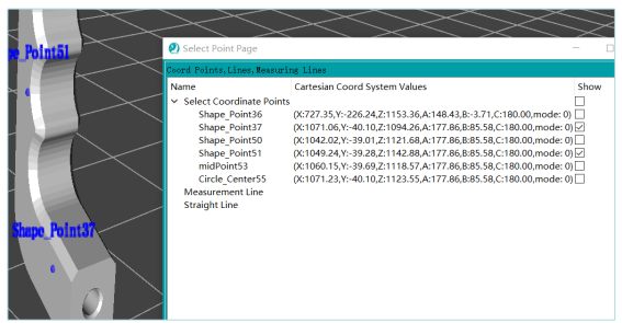
In the blank area of the simulation window, right-click and select "Show Selected Point Window" to open the point selection window.
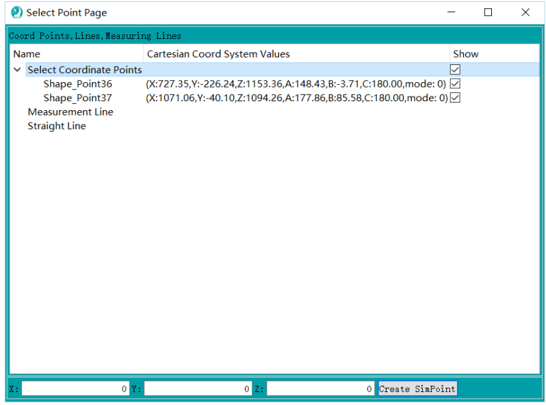
In this window, you can manage the created simulation points.
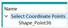
The Name column displays the name of the simulation point, which is currently not editable.
The Cartesian Coordinate System Value column displays the values of the simulation point, which are currently not editable

The Display column controls the visibility of the simulation point.

Right-clicking on a simulation point opens a context menu.
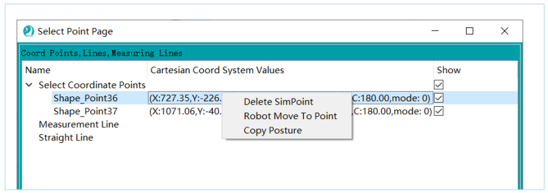
The functionality is consistent with the features described in section 9.7.7.
Press CTRL + left-click to select multiple data points.
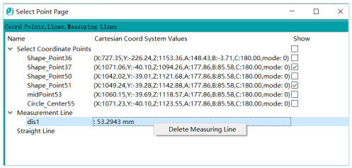
When there are two selected points, a right-click context menu will appear.
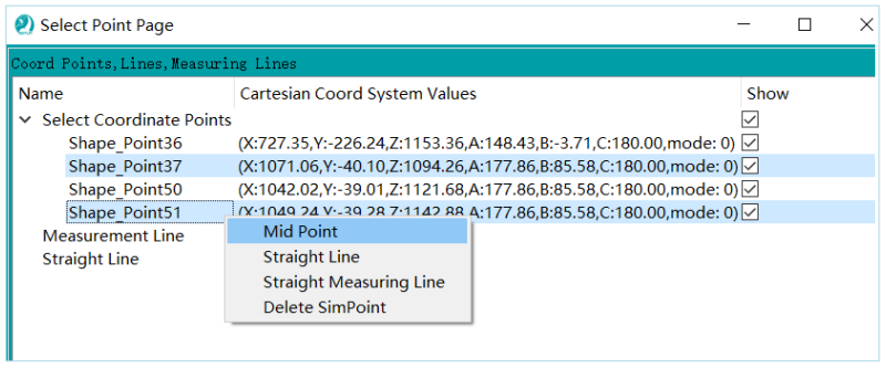
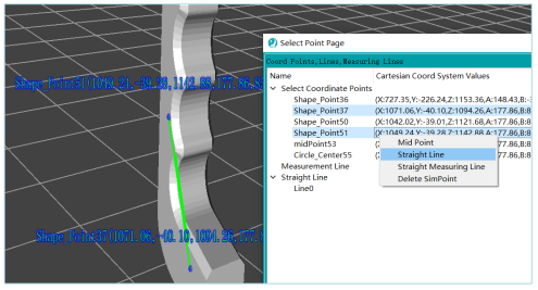
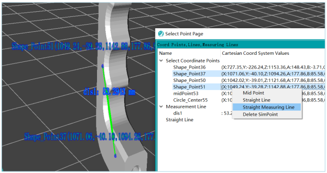
You can create a midpoint, a straight line, a linear measurement line (distance between two points), or delete the selected simulation points between the two points.
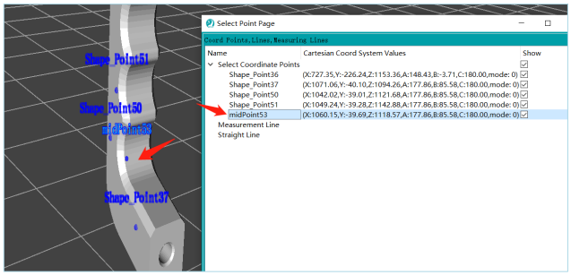
The midpoint between simulation point 37 and simulation point 51.
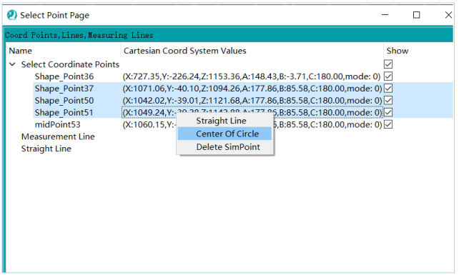
The center point of simulation points 37, 50, and 51.
The straight line between simulation points 1 and 2.
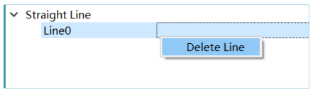
Delete Line
The linear measurement line between simulation points 37 and 51.
Right-clicking on the measurement line allows you to delete the line.
When there are 3 selected points, a right-click context menu will appear.
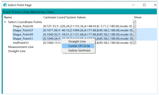
You can connect the 3 selected points in the order of selection with a straight line, create a center point, or delete the selected point models as a whole.
9.10.Collision Detection
For detailed usage of this feature, please refer to section 9.7.3.2.
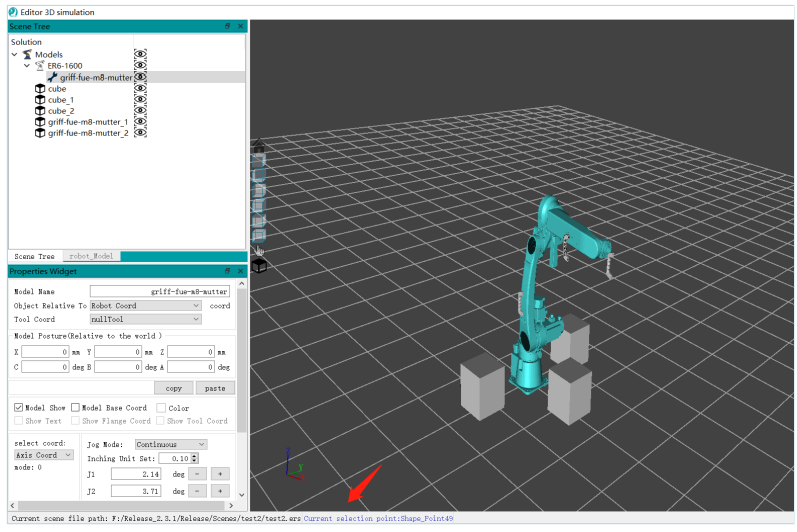
9.11.Window Status Bar
Displays the current path of the scene file.
9.12.Simplified 3D Window
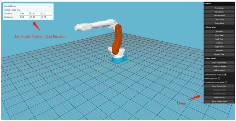
There is no need to use 3D complex functions. By watching the robot's rhythm, you can open the simplified version of 3D. The simplified version of 3D coordinate system is Z-axis up, X-axis forward, and right-hand coordinate system. The middle vertical axis, the blue axis represents the Z axis, the yellow axis represents the X axis, and the green axis represents the Y axis. Rotation: Left mouse button.
Zoom in: Mouse wheel. Pan: Right mouse button.
9.12.1.Model pose window bar
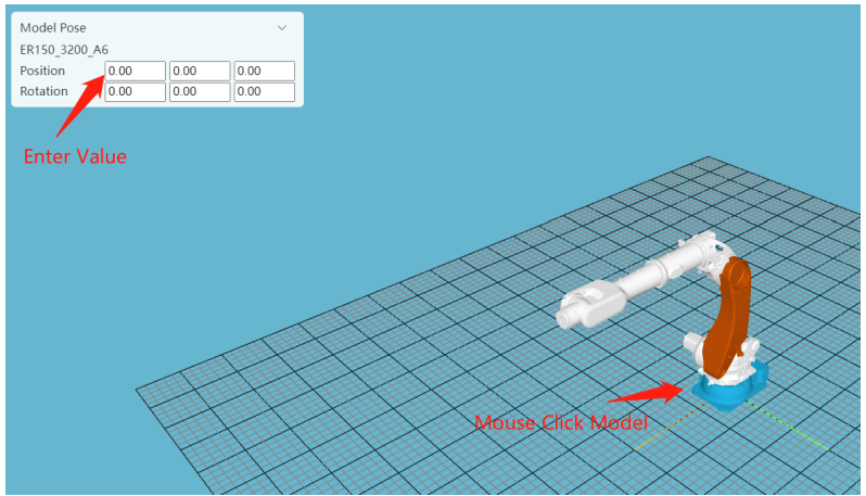
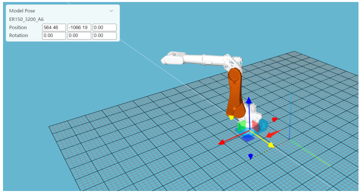
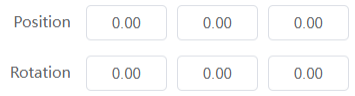
When the mouse clicks on the model, the base of the robot model will display blue, while other models will display blue, representing the currently selected model. This window displays the pose of the currently selected model,
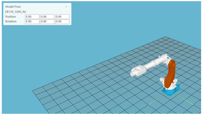
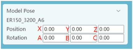
Model pose, which refers to the position data of the model relative to its parent node (if there is no parent node, it is the world coordinate system as the parent node);
Attitude: Attitude is the attitude data of the model relative to its parent node (if there is no parent node, it is the world coordinate system as the parent node);
Explanation of posture data:
Input field A refers to the rotation of the model's own coordinate system around the X-axis;
The input field B represents the rotation of the model's own coordinate system around the Y-axis;
The input field C represents the rotation of the model's own coordinate system around the Z-axis;
Click to modify the pose of the model to modify its current pose value.
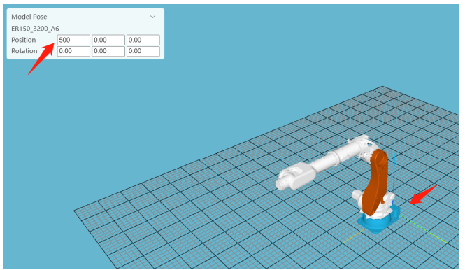
Complete numerical results
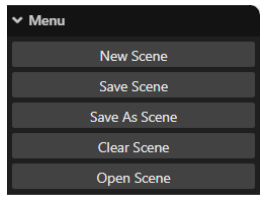
1. New scene
Click on "New Scene" and enter the scene name to create a new scene
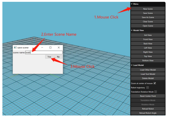
2. Save the scene
Click to save the scene, enter the scene name to save the current scene
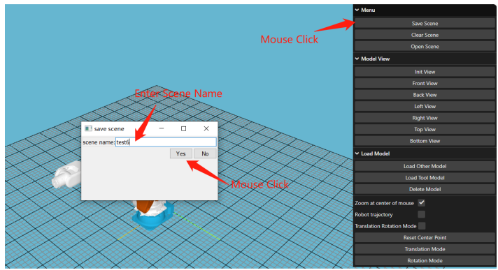
3. Save As Scene
Click Save Scene to save the currently opened scene as another scene file
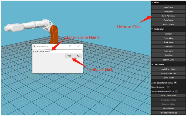
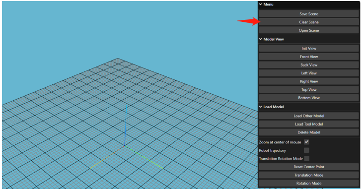
4. Clear the scene
Click Clear Scene to clear the current simplified 3D scene
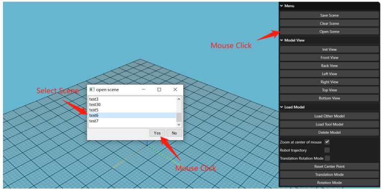
5. Open the scene
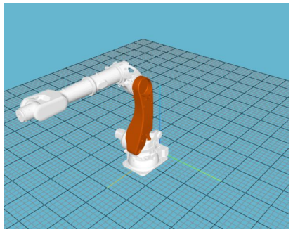
Click to open the scene and select the scene file to open the 3D model content of the scene file.
(2)Model View
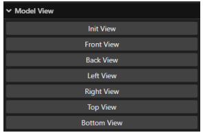
1. Init View
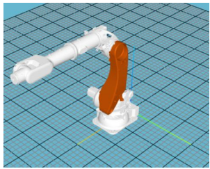
2. Front View
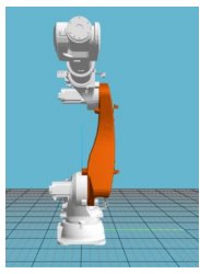
3. Back View
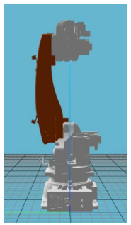
4. Left View
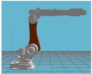
5. Right View
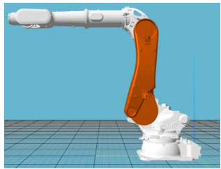
6. Top View
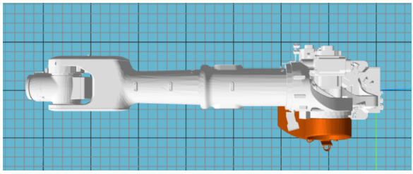
7. Bottom View
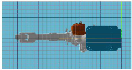
(3) Import Model
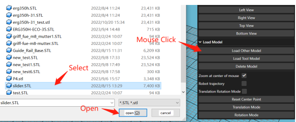
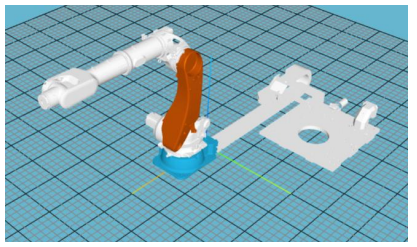
1. Import other models
Click to import other models to import regular models. Please note that the model name must start with a letter and cannot have special symbols such as Chinese or underscores.
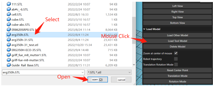
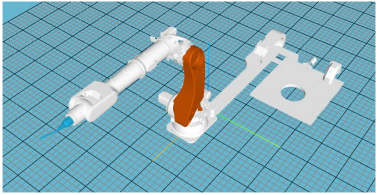
2. Import tool model
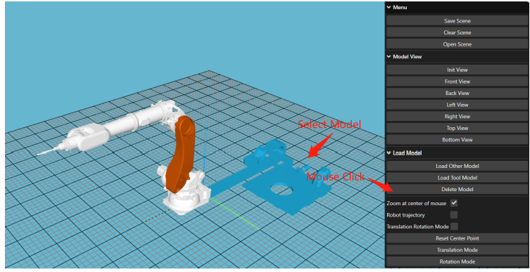
3. Delete Model
Click on the current model, and the current model will display in blue. Click Delete to delete the current odel.
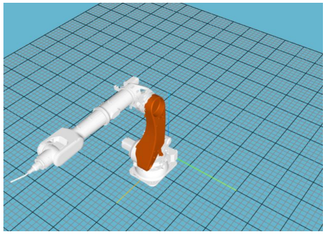
(4) Setting
1. Zoom around the mouse
The default is checked, unchecking will result in zooming to the center of the world

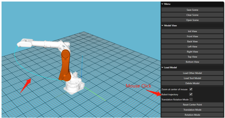
2. Robot trajectory
Click on the robot trajectory to display the tool end trajectory of the robot's movement. Uncheck to delete the previous robot trajectory.
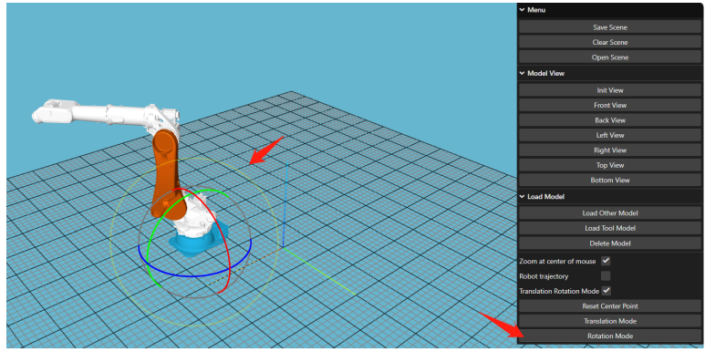
3. Translation and rotation mode of the model
Click on the model with the mouse, select the current model, and click to turn on the translation and rotation mode.
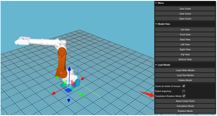
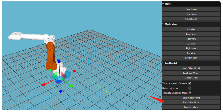
The default mode is pan mode,
The flat pattern represents the model, which can be moved by clicking on the pattern with the left mouse button and holding it down to move
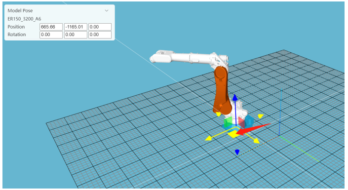
The arrow pattern represents moving the model along this axis. Click on the pattern with the left mouse button and hold down to move it.
Click the rotation mode button to switch the model rotation mode. Left click on the pattern and hold down to rotate the model
Click the pan button to switch back to pan mode.
After use, uncheck the translation and rotation mode to cancel the model movement mode.
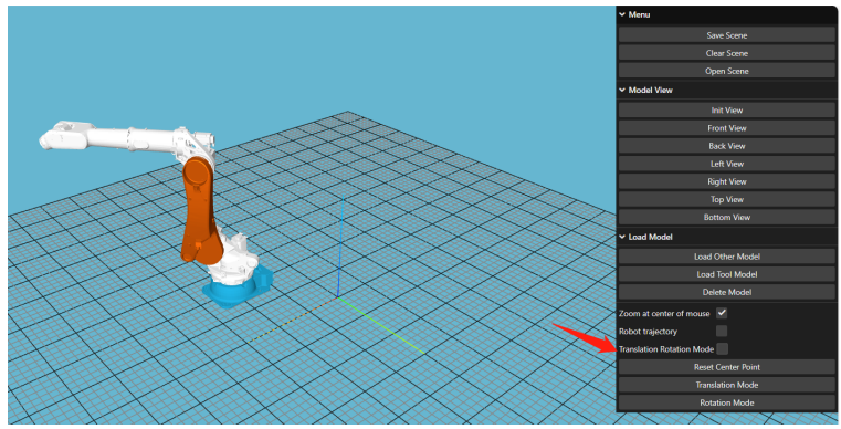
Note: When turning on the translation and rotation mode, manual input will not be allowed to modify numerical inputs.
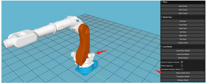
(5) Reset center point
Reset the rotation center by clicking on the position with the mouse, for convenient observation of objects.
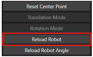
(6) Reload Robot
When connecting the robot controller, if the scene is cleared and the robot model is cleared, you can click this button to reload the robot model.
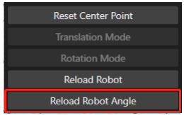
(7) Reload Robot Angle
When connecting the robot controller, if the scene is cleared and the robot model is cleared, after clicking the button  to load the robot, you can click this button to reload the angle value of the robot model.
9.12.3.Shortcut button
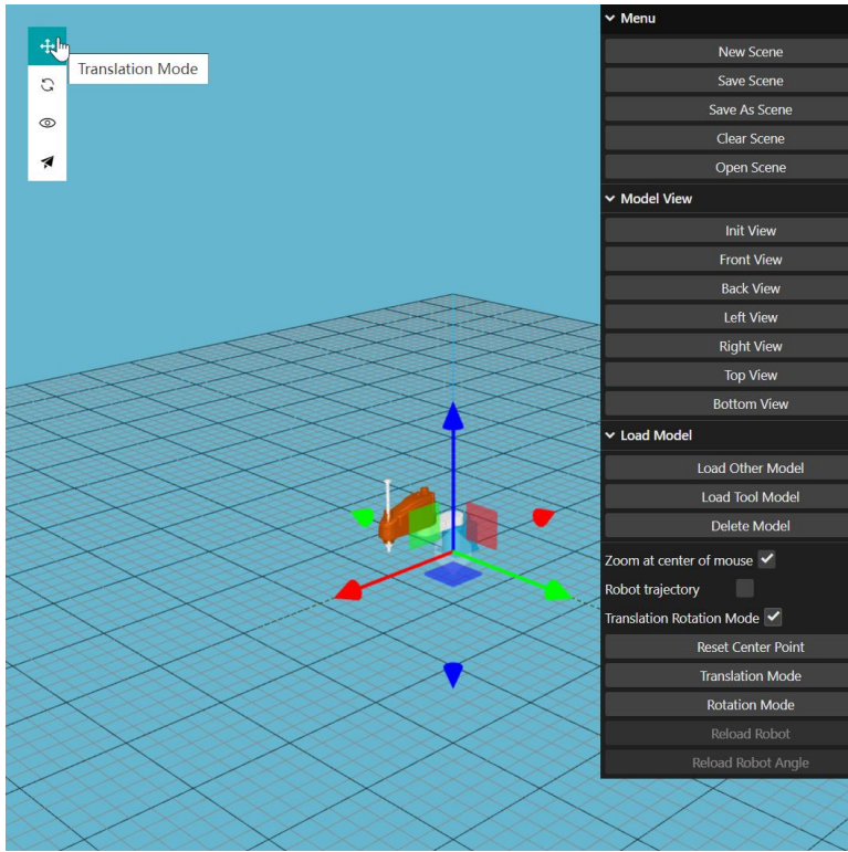
1. Click the "Translation" button to enter the translation mode when the "translation and rotation mode" is turned on, and the selected model can be translated, as shown in the figure below.
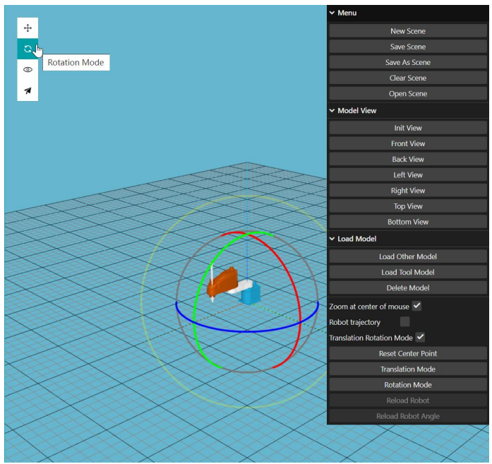
2. Click the "Rotation" button when the "Translation rotation mode" is turned on to enter the rotation mode, and the selected model can be rotated, as shown in the following figure.
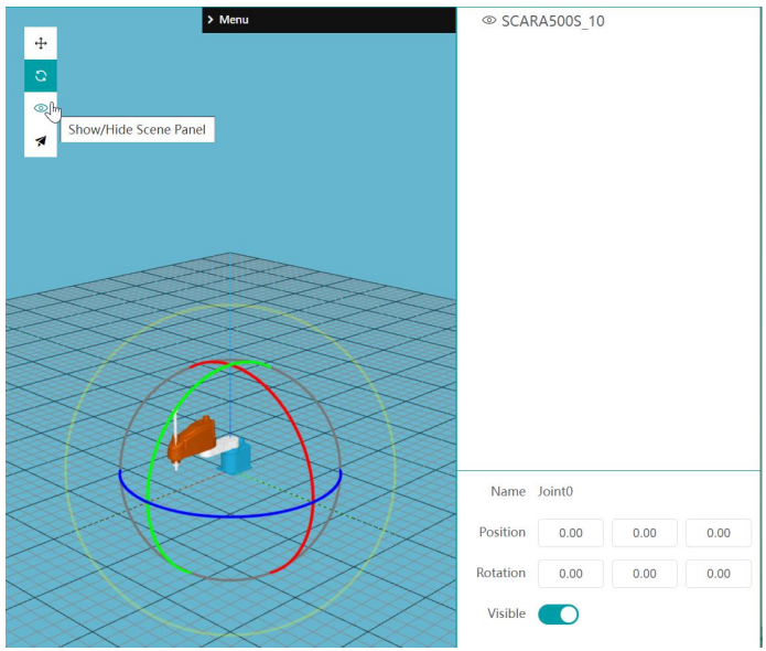
3. Click the "Show/Hide Scene Tree" button to display or hide the scene tree panel on the right, as shown below.
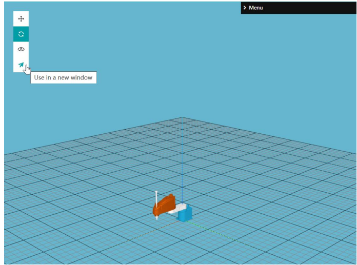
4. Click the "Open in a separate window" button to put 3D into a separate window for use, as shown below.
No comments to display
No comments to display