
8. Settings
8.1. Basic Settings
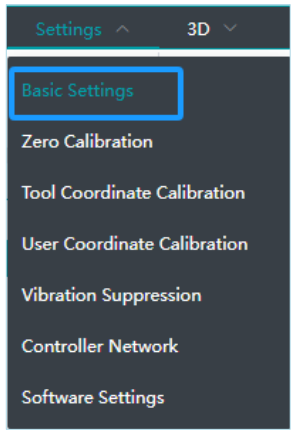
Startup Method: Settings→Basic Settings
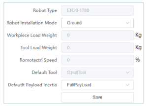
Set default parameters for the robot.
8.2. Zero Calibration
If the robot loses its zero point and cannot return to the correct position, you can perform zero calibration to obtain the zero point.
8.2.1. Startup Method
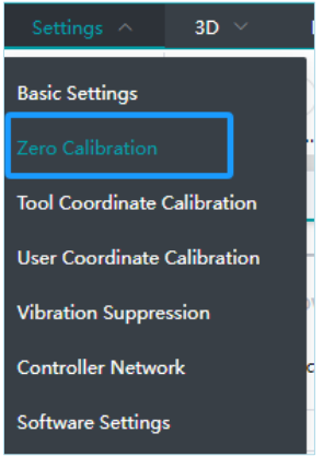
Startup Method: Settings → Zero Calibration
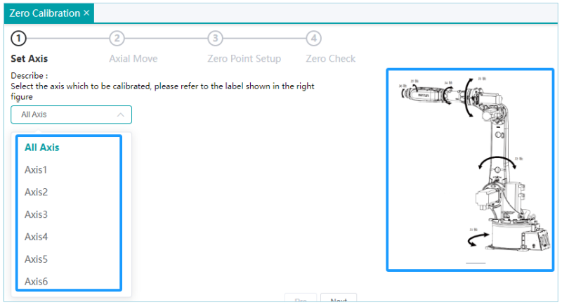
8.2.2.Select Axis
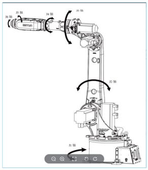
Select the axis which to be calibrated, please refer to the label shown in the right figure.
8.2.3. Axis Jogging
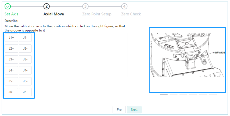
This interface is equipped with axis jog buttons for motorized adjustments, while displaying an image on the right side to facilitate axis zero-point calibration.
8.2.4. Zero Point Setup
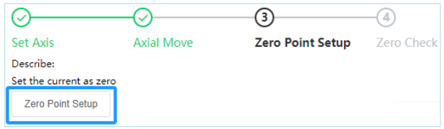
After completing the zero point calibration for all axes, click the 'Set Zero' button to define the current position as the reference point.
8.2.5. Zero Check
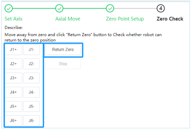
Within this feature, present a procedure for verifying the precision of the zero point. Users can displace the current zero point using the ‘Axis Jogging’ buttons and then execute a 'Return to Zero' test to assess the robot's ability to return to the zero point position.
在此功能下提供一个验证零点是否正确的步骤,使用者可通过点动按钮移开当前零点,点击返回零 点测试机器人是否可以回到零点位置。
8.3.Tool Coordinate Calibration
8.3.1.Startup Method
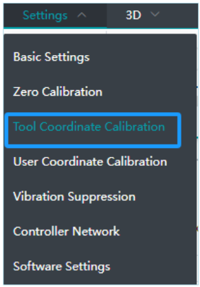
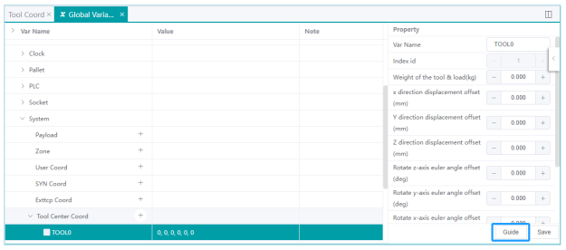
In the current software being employed, there are two distinct methods for initiating the calibration of the tool coordinate system:
(1) Settings → Tool Coordinate Calibration
(2) Establish a tool coordinate variable within the global parameters and initiate the tool coordinate calibration by clicking the wizard button at the designated variable location.
8.3.2.Solution Select
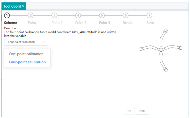
Tool coordinate calibration can be performed using two distinct methods:
(1) Four-Point Calibration: This method calibrates the tool's world coordinates (XYZ), without writing the ABC orientation into the variables.
(2) Single-Point Calibration: This method focuses on calibrating the orientation (ABC) of the tool coordinate, without affecting the XYZ coordinates stored in the variables.
8.3.3.Calibration Point
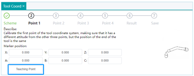
(1) Four-Point Calibration
The points used for calibrating the tool coordinate system consist of four in total. During calibration, it is essential to ensure that the orientation of the calibration point differs from the other three points, while maintaining an identical end effector position. This can be achieved by employing the teach pendant's point-to-point teaching functionality for the calibration points.
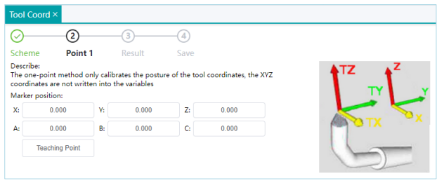
(2) One-Point Calibration
According to the visual representation in the image, calibrate the orientation (ABC) of the tool coordinate system.
8.3.4.Result
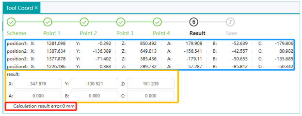
As an example of the four-point method, calculations are performed based on the four designated points, as shown in the diagram. The blue squares indicate the positions of the calibration points, the yellow squares represent the computed results of the calibration points, and the red squares depict the calculation errors associated with these results.
8.3.5.Save
If the computed results align with the expected values, proceed to the next step to access the results saving interface. Here, select the pre-established variables and click the 'Save' button to store the calculated results.
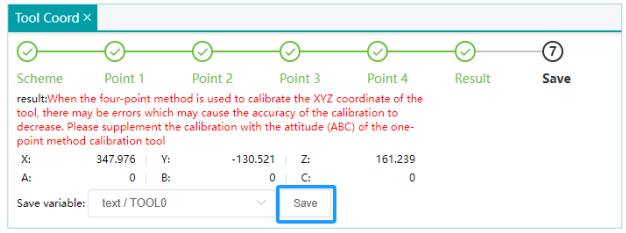

Caution: Employing the four-point method for calibrating the XYZ coordinates of the tool may introduce errors, potentially leading to a reduction in calibration accuracy. Therefore, it is recommended to complement the calibration process by incorporating the one-point method for orienting the tool (ABC).
8.4.User Coordinate Calibration
8.4.1.Startup Method
In the current software being employed, there are two distinct methods for initiating the calibration of the user coordinate system:
(1) Settings→User Coordinate Calibration;
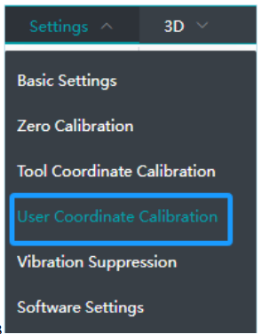
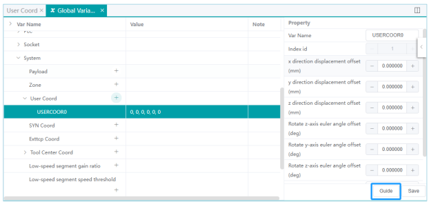
(2) Establish a user coordinate variable within the global parameters and initiate the user coordinate calibration by clicking the ‘Guide’ button at the designated variable location.
8.4.2.Origin
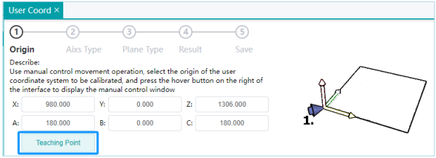
To establish the origin, you can employ quick manual control to swiftly navigate to the predetermined origin location. Then, press the 'Teaching Point' button to save the current position.
8.4.3.Axis Type
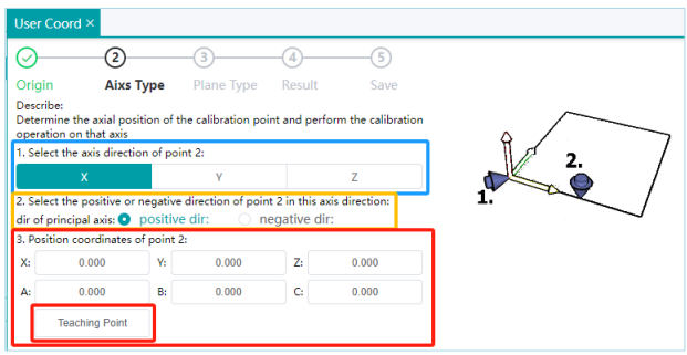
After establishing the origin point, the determination of axis types involves a three-step process:
(1) Identification of the axis type for Point 2, with options including X, Y, or Z, as illustrated within the blue outlined section in the diagram.
(2) Subsequent to determining the axis type, selecting whether the point lies along the positive or negative direction of that axis, as denoted in the yellow outlined section of the diagram.
(3) Calibration of Point 2 involves utilizing quick manual control (refer to section 7.1.1 for detailed instructions) to navigate to the corresponding point position. Save the position by clicking the 'Teaching Point' button, as indicated in the red outlined section of the diagram.
8.4.4.Plane Type
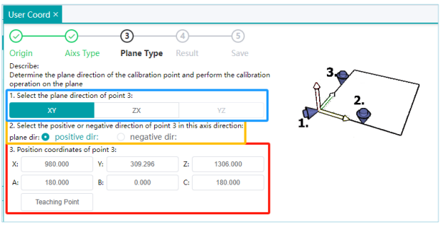
After ascertaining the axis type, the determination of the plane type follows a similar three-step procedure:
(1) Discern the specific plane type. For instance, if the X-axis was previously chosen, plane options encompass XY or XZ planes, delineated within the blue-framed section in the diagram.
(2) Subsequent to identifying the plane type, ascertain the orientation of Point 3 with respect to the selected plane. Taking the XY plane as an illustration, this step entails defining the directional placement of Point 3 along the Y-axis, as indicated in the yellow-framed section in the diagram.
(3) Execute the calibration of Point 3 by utilizing quick manual control to navigate to the corresponding positional marker. Safeguard the precise position by activating the 'Teach Point' function, represented in the redframed section of the diagram.
8.4.5.Result
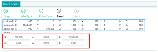
The outcome interface will delineate the spatial coordinates for the three reference points (as indicated within the blue-bordered section in the diagram) and autonomously compute the calibration outcomes, subsequently presenting them within the red-bordered section of the graphical representation.
8.4.6.Save
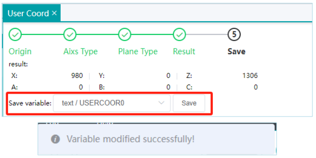
If the calibration results are error-free, select the pre-established user coordinate variable in the corresponding indicator box, and then save the calibration results by clicking the 'Save' button.
8.5.Vibration Suppression
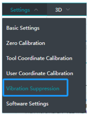
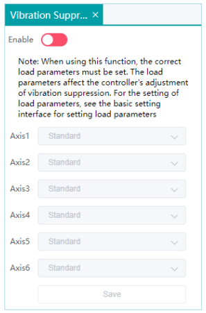
Startup Method: Settings→Vibration Suppression
Before utilizing this function, ensure that the load parameters are correctly configured. These parameters have a significant impact on the controller's adjustment for vibration suppression.
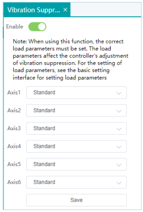
Please be aware that this feature is operable exclusively in the enabled state. In the disabled state, the proper functionality of this feature cannot be ensured.
8.6.Servo Parameters
8.6.1.Startup Method
Settings→User Coordinate Calibration;
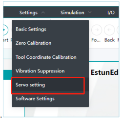
8.6.2.Clear Servo Warning
You can use this module to reset each axis and clear historical alarms.

8.6.3.Set Pn Parameters
You can use this module to set the Pn parameters for each axis.

8.6.4.Version Information
(1) Driver
You can obtain the ID, model, BOOT version, FPGA version, and DSP version of each axis servo

(2)IO
This module can obtain the ID, model, BOOT version, FPGA version, DSP version, and temperature of the IO module.

8.6.5.Backup and Recovery
This module can backup and restore servo parameters.

8.7.Software Settings
Startup Method:Settings→Software Settings
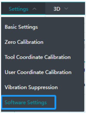
This section primarily deals with basic switches and configurations for various functional operations.
8.7.1.System Settings
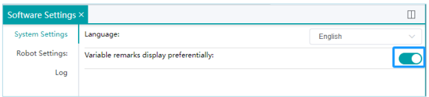
The system's configuration interface facilitates the modification of software language preferences. Estun Editor offers bilingual functionality, enabling the seamless transition between Chinese and English. Following the adjustment, a software reboot is necessitated to implement the language changes.
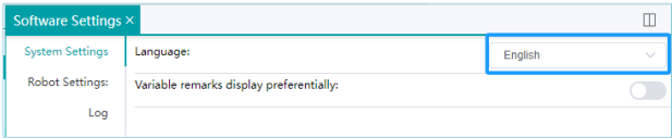
Concurrently, you have the option to configure the primary presentation of variable annotations by simply clicking the designated button.
8.7.2.Robot Settings
Robot settings offer the flexibility to modify the quantity of external axes.

8.7.3.Log
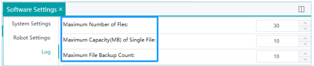
The log interface offers three configurable parameters:
(1) Maximum Number of Files: Defines the number of log files that can be cached, within the range of 0 to 100.
(2) Maximum Capacity (MB) of Single File: Specifies the maximum memory allocation for an individual file, ranging from 0 to 100MB.
(3) Maximum File Backup Count: Sets the maximum number of files that can be backed up, with a range of 0 to 100.
No comments to display
No comments to display